



 141 / 228

4. STRUCTURAL DESIGN OF LVL STRUCTURES
Normal stress from bending moment is calculated for
composite cross sections according to the equation:
σ_(i,d(z) )=(E_i 〖 ∙ e〗_(z)i ∙ M_d)/〖EI〗_eff
(4.86)
where
σ
i,d
is the design value of normal stress at coordinate z in the
section [N/mm
2
];
Ei
is the modulus of elasticity of a part i [N/mm2];
e
(z)i
is the coordinate z of the point i where the stress is
analysed = distance to the neutral axis of the entire
composite cross section [mm];
M
d
is the design value of the bending moment at the
evaluated location of the member [Nmm]; and
EI
eff
is the effective stiffness of the composite cross
section [Nmm
2
].
Shear stresses at the glued joints of composite cross sections are
calculated according to equation:
τ_(z)d=E_i∙(S_((z) ) ∙ V_d)/(〖EI〗_eff ∙〖 b〗_((z) ) ) (4.87)
where
τ
(z)d
is the design value of the shear stress at coordinate z in
the section [N/mm
2
];
Ei
is the modulus of elasticity of a part i [N/mm2];
S
(z)
is the static moment at coordinate z [mm³];
V
d
is the design value of shear force at the evaluated
location of the member [Nmm];
EI
eff
is the effective stiffness of the composite cross
section [Nmm
2
];
b
(z)
is the width of the section at coordinate z [mm];
S
(z)
=
∑
i
A
i
∙
e
(z)i
(4.88)
A
i
is the cross-sectional area of a part i [mm
2
]; and
e
(z)i
is the coordinate z of the point i where the stress is
analysed = distance to the neutral axis of the entire
composite cross section [mm].
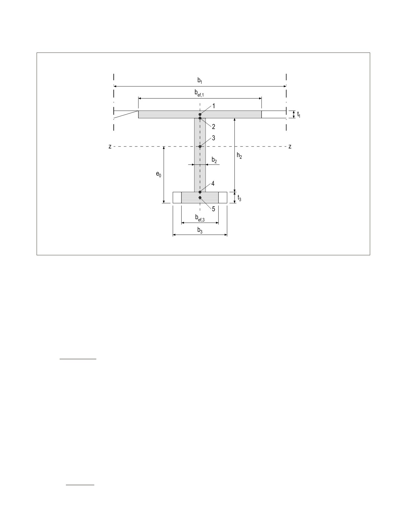
Figure 4.29.
Composite cross section. In thin-flanged beams axial stresses are checked at points 1, 3 and 5. Shear stresses are checked at points
2, 3 and 4.
0
=
∑
i
∙
i
∙
i
i
∑
i
∙
i
i
i,d(z)
=
i
∙
(z)i
∙
d eff
(z)d
=
i
∙
(z)
∙
d eff
∙
(z)
(z)
= ∑
i
∙
(z)i
i
165 (255)
I
i
is the moment of inertia of a part
i
[mm
4
], for rectangular cross section
I
i
=
b
i
∙h
i
3
/12
, where
b
i
is the width [mm] of the part and
h
i
is the height [mm] of the
part;
A
i
is the cross-sectional area of a part
i
[mm
2
]; and
e
i
is the eccentricity of the part
i
= distance between the centre of gravity of part
i
and neutral axis of the entire composite cross section [mm].
The location of the neutral axis of a composite cross section related to the bottom of the
section is:
0
= ∑
i
∙
i
∙
i
i
∑
i
∙
i
i
(4.85)
where
a
i
is the distance between the centre of gravity of part
i
and the bottom of the
entire composite cross section [mm].
or al stress from bending moment is calculated for composite cross sections according to
the equation:
i,d(z)
=
i
∙
(z)i
∙
d eff
(4.86)
where
σ
i,d
is the design value of normal stress at coordinate z in the section [N/mm
2
];
is the modulus of el sticity of a part
i
[N/mm
2
];
(
is the coordinate
z
of the point
i
where the stress is analy ed = distance to the
neutral axis of the entire composit cross section [mm];
M
d
is the design value of the bending moment at the evaluated location of the
member [Nmm]; and
EI
eff
is the effectiv stiffness of the composite cross section [Nmm
2
].
Shear stresses at the glued joints of composite cross sections are calculated accordi g to
equation:
(z)d
=
i
∙
(z)
∙
d
eff
∙
(z)
(4.87)
where
τ
(z)d
is the design value of the shear stress at coordinate z in the section [N/mm
2
];
i
2
n
( )
2
LVL Handbook Europe
139