



 136 / 228

4.3.12 Holes
Eurocode 5 does not provide instructions for designing holes
in beams, but such instructions are presented in the non-con-
flicting complementary instructions (NCCI) for Eurocode 5.
The designmethod presented in this subsection is based on the
Austrian NCCI document ÖNORM B 1995-1-1:2015, annex
F
33
and it can it be applied to holes in LVL beams in service
class 1 and 2 conditions. LVL suppliers have in their technical
documentation also their own tailored instructions for design-
ing holes in LVL beams with different boundary conditions.
For all beams with holes the bending, shear and tension/
compression resistance shall be verified at the location of the
hole. When the diameter d of the hole is ≥ 50 mmor ≥
h
/10, the
resistance against tension perpendicular to the grain shall be
verified by equation (4.57), shear stress concentration shall be
verified by equation (4.62). The bending stress at the location of
the hole shall be verified by equations (4.64) and (4.65) for rec-
tangular holes or (4.71) for round holes. The corners of rectan-
gular holes shall be a rounding radius
r
≥ 15 mm. The bound-
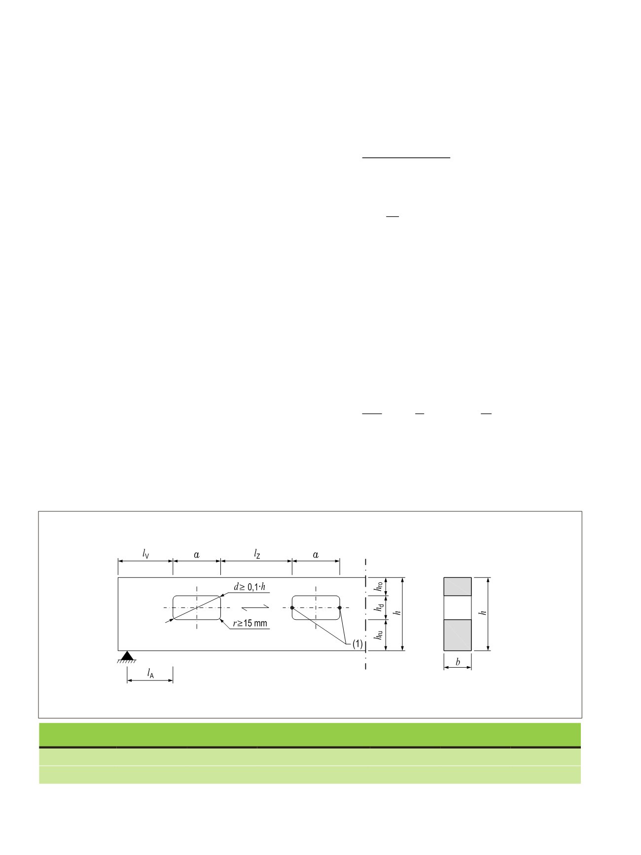
ary conditions of the geometry are specified in Figure 4.25.
The verification of the resistance against tension perpen-
dicular to the grain stresses can be the most critical condition
to fulfil in the design of holes in LVL-P beams. LVL-C beams,
on the other hand, offer a significant advantage for beams with
holes, as the cross veneers act as reinforcement around the
holes preventing cracking due to tension stresses perpendic-
ular to the grain. Their resistance is therefore superior and the
larger hole size limit for reinforced holes specified in the Aus-
trian NCCI document may be applied to LVL-C beams.
Tension stress perpendicular to the grain in verified by the
equation
σ_(t,90,d)=F_(t,90,d)/(0,5
(4.57)
where
k_(t,90)=min{█(1@(450/h)^0,5 )┤
(4.58)
σ
t,90,d
is the design value of tension stress perpendicular to the
grain [N/mm
2
];
F
t,90,d
is the design value of tension force perpendicular to the
grain [N];
l
t,90
is the load distribution length [mm], see Figure 4.26;
b
is the beam thickness [mm];
f
t,90,d
is the design value of tension strength perpendicular to
the grain [N/mm
2
]; and
h
is the beam height [mm].
The tension perpendicular to the grain force
F
t,90,d
depends on
the shear force
V
d
and bending moment
M
d
at the edge of the
hole:
F_(t,90,d)=(V_d∙h_d)/(4∙h)∙[3
(4.59)
where
h_r={█(min(h_ro;h_ru ) for rectang
(4.60)
t,90,d
=
t,90,d
0,5 ∙
t,90
∙ ∙
t,90
≤
t,90,d
t,90
= � 1 �
450 ℎ
�
0,5
t,90,d
=
d
∙ℎ
d
4∙ℎ
∙ �3 − �
ℎ
d
ℎ
�
2
� + 0,008 ∙
d
ℎ
r
ℎ
r
= �
min(ℎ
ro
; ℎ
ru
) for rectangular holes
min(ℎ
ro
+ 0,15 ∙ ; ℎ
ro
+ 0,15 ∙ ) for round holes
t,90
= � 0,5 ∙ (ℎ
d
+ ℎ) for rectangular holes
0,35 ∙ + 0,5 ∙ ℎ for round holes
d
=
τ
∙
1,5 ∙
d
∙ (ℎ−ℎ
d
)
≤
v,d
τ
= 1,85 ∙ �1 +
ℎ
� ∙ �
ℎ
d
ℎ
�
0,2
t,90,d
=
d
∙ℎ
d
4∙ℎ
∙ �3 − �
ℎ
d
ℎ
�
2
� + 0,008 ∙
d
ℎ
r
ℎ
r
= �
min(ℎ
ro
; ℎ
ru
) for rectangular holes
min(ℎ
ro
+ 0,15 ∙ ; ℎ
ro
+ 0,15 ∙ ) for round holes
t,90
= � 0,5 ∙ (ℎ
d
+ ℎ) for rectangular holes
0,35 ∙ + 0,5 ∙ ℎ for round holes
d
=
τ
∙
1,5 ∙
d
∙ (ℎ−ℎ
d
)
≤
v,d
τ
= 1,85 ∙ �1 +
ℎ
� ∙ �
ℎ
d
ℎ
�
0,2
4. STRUCTURAL DESIGN OF LVL STRUCTURES
Figure 4.25.
Geometrical boundary conditions of holes in beams
33
.
LVL 04, Figure 4.25
Product type
l
v
l
A
l
z
h
ro
and
h
ru
a
h
d
LVL-P
≥
h
≥
0,5 h
Max (≥1,5h; 300 mm)
≥
0,35 h
≤
2,5 h
d
≤
0,15 h
LVL-C
≥
h
≥
0,5 h
Max (≥1,5h; 300 mm)
≥
0,25 h
≤
2,5 h
d
≤
0,4 h
Product type
l
v
l
A
l
z
h
ro
and h
ru
LVL-P
≥ h
≥0,5h Max(≥1,5h; 300 mm)
≥0,35h
LVL-C
≥ h
≥0,5h Max(≥1,5h; 300 mm)
≥0,25h
Figure 4.25. Geometrical boundary conditions of holes in beams
33
(Ku
beams)
Tension stress perpendicular to the grain in verified by the equation
t,90,d
=
t,90,d
0,5 ∙
t,90
∙ ∙
t,90
≤
t,90,d
(4.57)
where
t,90
= { 1 (
450 ℎ
)
0,5
t,90,d
is the design value of tension stress perpendicular to the
t,90,d
is the design value of tension force perpendicular to the g
t,90
is the load distribution length [mm], see Figure 4.26;
b
i the beam thicknes [mm];
t,90,d
is the design value of tension strength perpendicular to th
134
LVL Handbook Europe