



 134 / 228

4. STRUCTURAL DESIGN OF LVL STRUCTURES
4.3.11 Tapered beams
The influence of the taper on the bending stresses parallel to
the surface shall be taken into account.
The design bending stresses,
σ
m,α,d
and
σ
m,0,d
(see Figure
4.21) may be taken as:
σ_(m,α,d)=σ_(m,0,d)=(6M_d)/(bh^2 )
(4.49) (EC5 6.37)
At the outermost fibre of the tapered edge, the stresses
should satisfy the following expression:
σ_(m,α,d)≤k_(m,α)∙f_(m,d)
(4.50) (EC5 6.38)
where
σ
m,α,d
is the design bending stress at an angle to grain;
f
m,d
is the design bending strength; and
k
m,α
is calculated as follows:
For tensile stresses parallel to the tapered edge:
k_(m,α)=1/√(1 + (f_(m,
(4.51)
32
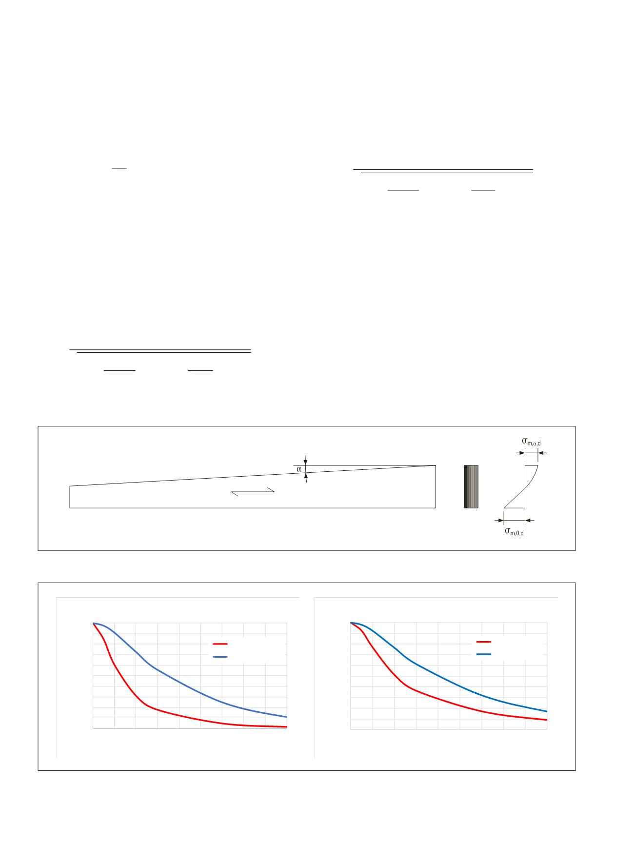
Figure 4.21.
Single-tapered beam. α is the angle between the tapered edge and the grain direction of the beam (EC5 Figure 6.8).
where
a={█(0,75 for LVL-P@1,0 for LVL-C)┤
(4.52)
32
For compressive stresses parallel to the tapered edge:
k_(m,α)=1/√(1 + (f_(m,d
(4.53)
32
where
b={█(1,5 for LVL-P@1,0 for LVL-C)┤
(4.54)
32
It is not necessary to take km,α into consideration in the
resistance against lateral torsional buckling of the beam equa-
tion (4.38). The effects of combined axial force and bending
moment shall be taken into account. When the tapered edge
is under tension stress, km,α is used to reduce the bending
strength in the equations for combined stresses equation (4.17)
and (4.18). When the tapered edge is under compression stress,
k
m,α
is used to reduce the bending strength in the equations for
combined stresses equations (4.19) and (4.20).
0,0
0,1
0,2
0,3
0,4
0,5
0,6
0,7
0,8
0,9
1,0
0
5 10 15 20 25 30 35 40 45
Reduction factor k
m,α
α
LVL 48 P
km,α,tension
km,α,compression
0,0
0,1
0,2
0,3
0,4
0,5
0,6
0,7
0,8
0,9
1,0
0
5 10 15 20 25 30 35 40 45
Reduction factor k
m,α
α
LVL 36 C
km,α,tension
km,α,compression
Figure 4.22.
Strength reduction factor
k
m,α
for tensile or compression stress parallel to the tapered edge. Left LVL 48 P, right LVL 36 C.
m,α,d
=
m,0,d
=
6
d
ℎ
2
(4.49) (EC5 6.37)
m,α,d
≤
m,α
∙
m,d
(4.50) (EC5 6.38)
m,α
=
1
�1 + �
m,d ∙ v,d
tan �
2
+ �
m,d t,90,d
tan
2
�
2
(4.51)
32
m,α,d
=
m,0,d
=
6
d
ℎ
2
(4.49) (EC5 6.37)
m,α,d
≤
m,α
∙
m,d
(4.50) (EC5 6.38)
m,α
=
1
�1 + �
m,d ∙ v,d
tan �
2
+ �
m,d t,90,d
tan
2
�
2
(4.51)
32
= � 0,75 for LVL − P
1,0 for LVL − C
(4.5
m,α
=
1
�1 + �
m,d ∙ v,d
tan �
2
+ �
m,d c,90,d
tan
2
�
2
= � 1,5 for LVL − P
1,0 for LVL − C
v,max,d
=
m,0,max,d
∙ tan
90,max,d
=
m,0,max,d
∙ tan
2
= � 0,75 for LVL − P
1,0 for LVL − C
(4.5
m,α
=
1
�1 + �
m,d ∙ v,d
tan �
2
+ �
m,d c,90,d
tan
2
�
2
= � 1,5 for LVL − P
1,0 for LVL − C
v,max,d
=
m,0,max,d
∙ tan
90,max,d
=
m,0,max,d
∙ tan
2
155 (255)
,
=
1
√1 + (
m,d
∙
v,d
tan )
2
+ (
m,d t,90,d
tan
2
)
2
(4.51)
32
where
= { 0,75 for LVL − P
1,0 for LVL − C
(4.52)
32
For compressive stresses parallel to the tapered edge:
m,α
=
1
√1 + (
m,d
∙
v,d
tan )
2
+ (
m,d c,90,d
tan
2
)
2
(4.53)
32
Where
= { 1,5 for LVL − P
1,0 for LVL − C
(4.54)
32
It is not necessary to take
k
m,
α
into consideration in the resistance against lateral torsional
buckling of the beam equation (4.38). The effects of combined axial force and bending
moment shall be taken into account. When the tapered edge is under tension stress,
k
m,
α
is
used to reduce the bending strength in the equations for combined stresses equation (4.17)
and (4.18)
.
When the tapered edge is under compression stress,
k
m,
α
is used to reduce the
bending strength in the equations for combined stresses equations (4.19) and (4.20).
It is recommended to have the tapered edge on the compressive side, especially for LVL-P,
since the tension perpendicular to grain strength
f
t,90,edge,k
is low, which can lead to cracks and
brittle failure. LVL-C may be used for special shapes, also when the tapered edge is on the
tensile side, as its
f
t,90,edge,k
is higher due to the cross veneers and it behaves more ductile.
Figure 4.21 shows the
k
m,α
factors as a function of the angle
α
.
m,α
√1 + (
m,d
∙
v,d
tan )
2
+ (
m,d t,90,d
tan
2
)
2
(4.51)
32
where
= { 0,75 for LVL P
1,0 for LVL C
For compressive stresses parallel to the tapered edge:
,
=
1
√1 + (
m,d
∙
v,d
tan )
2
+ (
m,d c,90,d
tan
2
)
2
(4.53)
32
Where
= { 1,5 for LVL − P
1,0 for LVL − C
It is not necessary to take
k
m,
α
into onsideration in the resistance agai
buckling of the beam equation (4.38). The effects of combined axial for
e t shall be taken into account. When the tapered edge is under t
used to reduce the bending strength in the equations for combined stre
and (4.18)
.
When the tapered edge is under compression stress,
k
m,
α
is
bending strength in the equations for combined stresses equations (4.
It is recommended to have the tapered edge on the compressive side,
since the tension perpendicular to grain strength
f
t,90,edge,k
is low, which
brittle failure. LVL-C may be used for special shapes, also when the ta
tensile side, as its
f
t,90,edge,k
is higher due to the cross veneers and it be
Figure 4.21 shows the
k
m,α
factors as a function of the angle
α
.
Figure 4.21. Strength reduction factor k
m,α
for tensile or compression st
tapered edge. Left LVL 48 P, right LVL 36 C.
For high pitched roof beams (
α
≥ ~10°) the maximum shear stress
v,m
perpendicular to the grain
90,max,d
shall be calculated at the point of th
moment stress with the equations:
132
LVL Handbook Europe