



 139 / 228

4. STRUCTURAL DESIGN OF LVL STRUCTURES
Table 4.10.
Example limiting values for beam deflection.
Deflection due to bending moment and shear should be taken
into account for all load-bearing timber products. As an ex-
ample, the deflection of a single-span beam under uniformly
distributed load is calculated from equation:
w=(5 〖∙ q〗_(d,i,SLS) ∙ L^4)/(〖384 ∙
(4.74)
and for a point load in the middle of the span
w=(F_(d,i,SLS) ∙ L^3)/(〖48 ∙ E〗
(4.75)
where
q
d,i,SLS
is the design value of a uniformly distributed action in
serviceability limit state [N/mm];
F
d,i,SLS
is the design value of a point load in serviceability
limit state [N/mm];
L
is the span of the beam [mm];
I
is the moment of inertia of the LVL cross section
[mm
4
];
A
is the cross-sectional area of the LVL beam [mm
2
];
ζ
is the shear deformation factor, for rectangular cross
section
ζ
= 6/5
E
mean
is the mean value of the modulus of elasticity of the
LVL class [N/mm
2
]; and
G
mean
is the mean value of the modulus of rigidity of the LVL
class [N/mm
2
].
Instructions for the deflection calculation of other loading and
span configurations can be found, e.g, from general handbooks
on mechanics or can be calculated with FEM calculation soft-
ware.
Note: In the EN standards modulus of elasticity E is defined as
the local value, E
local
, which does not include shear deflection.
Therefore shear deflection needs to be calculated separately, see
equation (4.75) and (4.76). Another way to define modulus of
elasticity is the global value, E
global
, in which shear deflection is
included. In edgewise bending of LVL the value of E
global
is about
5-7% smaller than E
local
, but its use makes the calculation easier,
because separate calculation of shear deformation is not need-
ed. E
global
is commonly used in e.g. Australia and USA. Another
name for E
global
is E
apparent
and another name for E
local
is E
true
.
4.3.14 Serviceability limit state design:
Floor vibrations
Eurocode 5, Section 7.3.3, gives requirements and some in-
structions for the design of residential floors. However, most
national annexes deviate significantly from these.
Wooden floor structures can be divided into high frequen-
cy floors and low frequency floors based on their lowest fun-
damental frequency.
For residential floors with a fundamental frequency great-
er than 8 Hz (f1 > 8 Hz), the following requirements should
be satisfied:
w/F≤a [mm/kN]
(4.76) (EC5 7.3)
and
v≤b^(〖(f〗_1 ξ-1)) [m/Ns2]
(4.77) (EC5 7.4)
where
w
is the maximum instantaneous vertical deflection
caused by a vertical concentrated static force F applied at
any point on the floor, taking account of load
distribution;
v
is the unit impulse velocity response, i.e. the maximum
initial value of the vertical floor vibration velocity (in
m/s) caused by an ideal unit impulse (1 Ns) applied
at the point of the floor giving maximum response.
Components above 40 Hz may be disregarded; and
ζ
is the modal damping ratio.
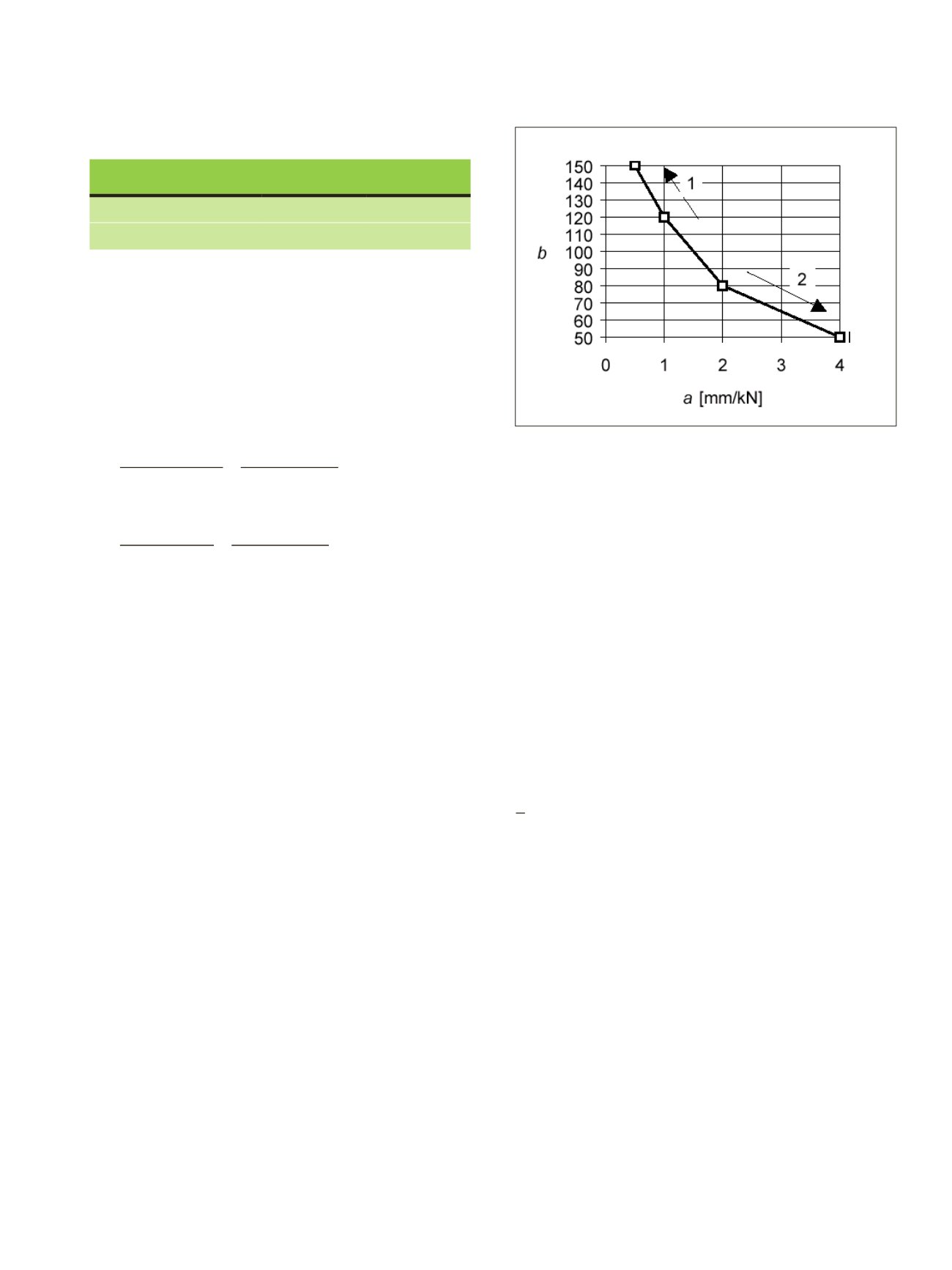
Values for factors a and b can be chosen from the diagram in
Figure 4.28 depending on the desired performance level.
Figure 4.28.
Recommended range of and relationship between
a and b. Performance improves in the arrow 1 direction and
decreases in the arrow 2 direction (EC5 Figure 7.2).
≤
/kN]
≤
(
1
−1)
[m/Ns
2
]
≤
[mm/kN]
≤
(
1
−1)
[m/Ns
2
]
w
inst
w
net,fin
Beam on two supports
l/300 to l/500 l/250 to l/350
Cantilevering beams
l/150 to l/250 l/125 to l/150
Figure 4.27 Components of deflection of LVL members
(Kuva_98 deflection
190401)
Note: LVL is not pre-cambered. Only in some very special cases LVL beams may be cut to a
camber by special sawing from an LVL billet.
The net deflection below a straight line between the supports,
w
net,fin
, should be taken as:
net, fin
=
inst
+
creep
(4.73)
Note: The recommended range of limiting values of deflections for beams with span
l
is given
in Table 4.10 depending upon the level of deformation deemed to be acceptable. Information
on national limit v lues can be found in the National Annex for Eurocode 5.
Table 4.10. Example limiting values for beam deflection.
w
inst
w
net,fin
Beam on two
supports
l/300 to l/500
l/250 to l/350
Cantilevering beams
l/150 to l/250
l/125 to l/150
Deflection due to bending moment and shear should b taken into account for all load-
bearing timber products. As an example, the deflection of a single-span beam under
uniformly distributed load is calculated from equation:
= 5 ∙
d,i,SLS
∙
4
384 ∙
mean
∙ + ∙
d,i,SLS
∙
2
8 ∙
mean
∙
(4.74)
and for a point load in the middle of the span
=
d,i,SLS
∙
3
48 ∙
mean
∙ + ∙
d,i,SLS
∙
2
4 ∙
mean
∙
(4.75)
where
q
is the design value of uniformly distributed action i serviceability limit state
[N/mm];
F
d,i,SLS
is the design value of a point load in serviceability limit state [N/mm];
L
is the span of the beam [mm];
I
is the moment of inertia of the LVL cross section [mm
4
];
A
is the cross-sectional area of the LVL beam [mm
2
];
ζ
is the shear deformation factor, for rectangular cross section ζ = 6/5
E
mean
is the mean value of the modulus of elasticity of the LVL class [N/mm
2
]; and
G
mean
is the mean value of the modulus of rigidity of the LVL class [N/mm
2
].
Instructions for the deflection calculation of other loading and span configurations can be
found, e.g, from general handb oks on mechanics or can be calculated with FEM calculation
software.
Note: In the EN standards modulus of elasticity
E
is defined as the local value,
E
local
, which
does not include shear deflection. Therefore shear deflection needs to be calculated
separately, see equation (4.75) and (4.76). Another way to define modulus of elasticity is the
global v lue,
E
global
, in which shear deflection is included. In edge ise bending of LVL the
v lue of
E
global
is about 5-7% smaller than
E
local
, but its use makes the alculation asier,
190401)
Note: LVL is not pre-cambered. Only in some very special cases LVL beams may be cut to a
camber by special sawing from an LVL billet.
The net deflection below a straight line between the supports,
w
net,fin
, should be taken as:
net, fin
=
inst
+
creep
(4.73)
Note: The recommended range of limiting values of deflections for beams with span
l
is given
in Table 4.10 depending upon the level of deformation deemed to be acceptable. Information
on national limit values can be found in the National Annex for Eurocode 5.
Table 4.10. Example limiting values for beam deflection.
w
inst
w
net,fin
Beam on two
supports
l/300 to l/500
l/250 to l/350
Cantilevering beams
l/150 to l/250
l/125 to l/150
Deflection due to bending moment and shear should be taken into account for all load-
bearing timber products. As an example, the deflection of a single-span beam under
uniformly distributed load is calculated from equation:
= 5 ∙
d,i,SLS
∙
4
384 ∙
mean
∙ + ∙
d,i,SLS
∙
2
8 ∙
mean
∙
(4.74)
and for a point load in the middle of the span
=
d,i,SLS
∙
3
48 ∙
mean
∙ + ∙
d,i,SLS
∙
2
4 ∙
mean
∙
(4.75)
r
q
d,i,SLS
is the design value of a uniformly distributed action in serviceability limit state
[N/mm];
F
d,i,SLS
is the design value of a point load in serviceability limit state [N/mm];
L
is the span of the beam [mm];
I
is the moment of inertia of the LVL cross section [mm
4
];
A
is the cross-sectional area of the LVL beam [mm
2
];
ζ
is the shear deformation factor, for rectangular cross section ζ = 6/5
E
mean
is the mean value of the modulus of elasticity of the LVL class [N/mm
2
]; and
G
mean
is the mean value of the modulus of rigidity of the LVL cla s [N/mm
2
].
Instructions for the deflection calculation of other loading and span configurations can be
found, e.g, from general handbooks on mechanics or can be calculated with FEM calculation
software.
Note: In the EN standards modulus of elasticity
E
is defined as the local value,
E
local
, which
does not include shear deflection. Therefore shear deflection needs to be calculated
separately, see equation (4.75) and (4.76). Another way to define modulus of elasticity is the
global value,
E
global
, in which shear deflection is included. In edge ise bending of LVL the
value of
E
global
is about 5-7% smaller than
E
local
, but its use makes the calculation easier,
LVL Handbook Europe
137