



 143 / 228

4. STRUCTURAL DESIGN OF LVL STRUCTURES
4.4.3 Multiple-glued GLVL panels
In GLVL-C panels the mechanical properties are declared as
homogenized values for the cross section assuming the cross
veneers as zero layers. The cross layers are thin and a gam-
ma method of effective cross section is not needed for mul-
tiple-glued GLVL-C panels when the LVL-C layers are all in
the same direction. They can be designed based on the me-
chanical values of the LVL components with the addition that
a size effect shall be taken into account for the flatwise bending
strength and flatwise shear strengths. The reference sizes and
size effect parameters
s, s
flat,m
and
s
flat,v
are declared in manu-
facturers’ technical documentation.
4.4.4 Rib slabs and box slabs
LVL rib slab and box slab elements have LVL-P ribs and LVL-C
panels that distribute the loads to the ribs and work as thin
flanges of the composite cross sections. Structural design is
made separately for each rib section. Their specific design in-
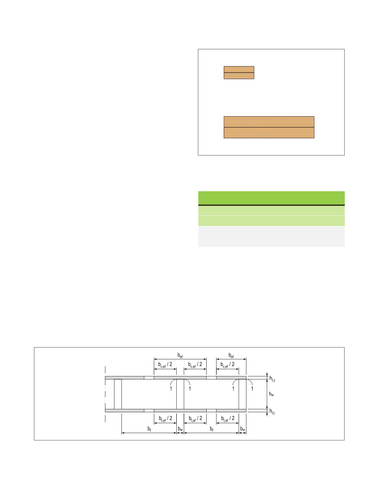
structions are given in Eurocode 5, clause 9.1.2. The effective
width bef of the flange panel that can be taken into account
in the calculations is limited due to shear lag and due to plate
buckling in ULS design on the compression side according to
Table 4.11.
In ULS design the following verifications are required:
• The mean axial compression stress
σ
f,c,d
and tension stress
σf,c,d shall be smaller than
f
f,c,d
and
f
f,c,d
strengths respective-
ly. Since the flange panels are thin, it is not required to verify
the resistance against tension and compression stresses at the
extreme fibres of the flanges.
• Resistance against shear stress for the ribs at the neutral ax-
is and with the equation (9.14) of Eurocode 5 for the glued
joints between the ribs and flange panels. The critical mate-
rial property is typically the flatwise shear strength
f
v,flat,0,d
of the flanges due to the rolling shear of the cross veneers
in LVL-C.
• Resistance against bending and shear stress of the flange
panels in the perpendicular direction of the slab
Figure 4.32.
Multiple-glued GLVL panels.
Table 4.11.
Maximum effective width bef of flange LVL-C panel
parallel to the ribs (Modified from EC5 Table 9.1).
Figure 4.33.
Definitions of the parts of rib slab part (EC5, Figure 9.2). I-section is used for the intermediate rib and C-section for the edge rib of
the element.
In SLS design, bending and shear deformations are tak-
en into account. For simplicity, the shear rigidity GA may be
evaluated based on the ribs only. In that case, the
k
def
factor of
LVL-P can also be used for the LVL-C flange panels in the flat-
wise direction in the calculation of final deformation, as the
thin flanges are mainly axially loaded.
Rib slab suppliers also have more advanced design instruc-
tions tailored and approved for their elements as part of their
technical documentation.
LVL 04, Table 4.11
Shear lag
Plate buckling in ULS design
I-section
b
ef
=
b
w
+ 0,1 ∙
l
b
ef
=
b
w
+ 20 ∙
h
f,c
C-section
b
ef
=
b
w
+ 0,05∙
l
b
ef
=
b
w
+ 10 ∙
h
f,c
Where
b
w
is rib thickness,
l
is span length and
h
f,c
is the
thickness of the flange panel on the compression side.
LVL Handbook Europe
141