



 138 / 228

4. STRUCTURAL DESIGN OF LVL STRUCTURES
4.3.13 Serviceability limit state design:
Deflections
Instantaneous deflection of a member is calculated using the
actions in equation (4.1). In serviceability limit state (SLS) the
partial safety factors
γ
G
and
γ
Q
of loads are 1,0. The following
serviceability limit state principles are defined in Eurocode 5,
clause 2.2.3:
The deformation of a structure resulting from the effects of
actions (such as axial and shear forces, bending moments and
joint slip) and from moisture shall remain within appropriate
limits, having regard to the possibility of damage to surfacing
materials, ceilings, floors, partitions and finishes, and to the
functional needs as well as any appearance requirements.
Instantaneous deformation, uinst, see Figure 4.27, should
be calculated for the characteristic combination of actions, see
EN 1990:2002, clause 6.5.3(2) a), using mean values of the ap-
propriate moduli of elasticity, shear moduli and slip moduli.
Final deformation
u
fin
, see e.g.
w
fin
in Figure 4.27, should
be calculated by superimposing the creep deformation ucreep
calculated using the quasi-permanent combination of actions,
see EN 1990:2002, 6.5.3(2)(c), onto the instantaneous defor-
mation uinst calculated from 2.2.3(2). The creep deformation
should be calculated using mean values of the appropriate
moduli of elasticity, shear moduli and slip moduli and the rel-
evant values of
k
def
given in Table 4.3.
Note: When calculating the creep deflection of LVL-C in the edge-
wise direction, the k
def
value is similar to LVL-P. In flatwise di-
rection, the k
def
is larger due to the rolling shear deformation of
the cross veneers, similar to plywood, see Table 4.3 of k
def
values.
If the structure consists of members or components having dif-
ferent creep behaviour, the long-term deformation due to the
quasi-permanent combination of actions should be calculated
using the final mean values of the appropriate moduli of elas-
ticity, shear moduli and slip moduli according to Eurocode 5,
clause 2.3.2.2 (1). The final deformation ufin is then calculated
by superimposing the instantaneous deformation, due to the
difference between the characteristic and the quasi-permanent
combination of actions on the long-term deformation.
For structures consisting of members, components and
connections with the same creep behaviour and under the
assumption of a linear relationship between the actions and
the corresponding deformations, as a simplification of EN
1990:2002, 2.2.3(3), the final deformation,
u
fin
, may be taken as:
u_fin=u_(fin,G)+u_(fi
(4.72) (EC5 2.2)
where
u
fin,G
=
u
inst,G
(1+
k
def
)
for a permanent action G;
u
fin,Q1
=
u
inst,Q1
(1+
ψ
2,1
k
def
) for the leading variable action, Q
1
;
u
fin,Qi
=
u
inst,Qi
(
ψ
0,i
+
ψ
2,i
k
def
) for accompanying variable
actions, Qi (i>1);
u
inst,G
,
u
inst,Q1
,
u
inst,Q,i
are the instantaneous
deformations for actions G,Q
1
,Q
i
respectively;
ψ
2,1
,
ψ
2,i
are the factors for the quasi-
permanent value of variable
actions;
ψ
0,i
are the factors for the combination
value of variable actions; and
k
def
is the creep deformation factor for
timber and wood-basedmaterials.
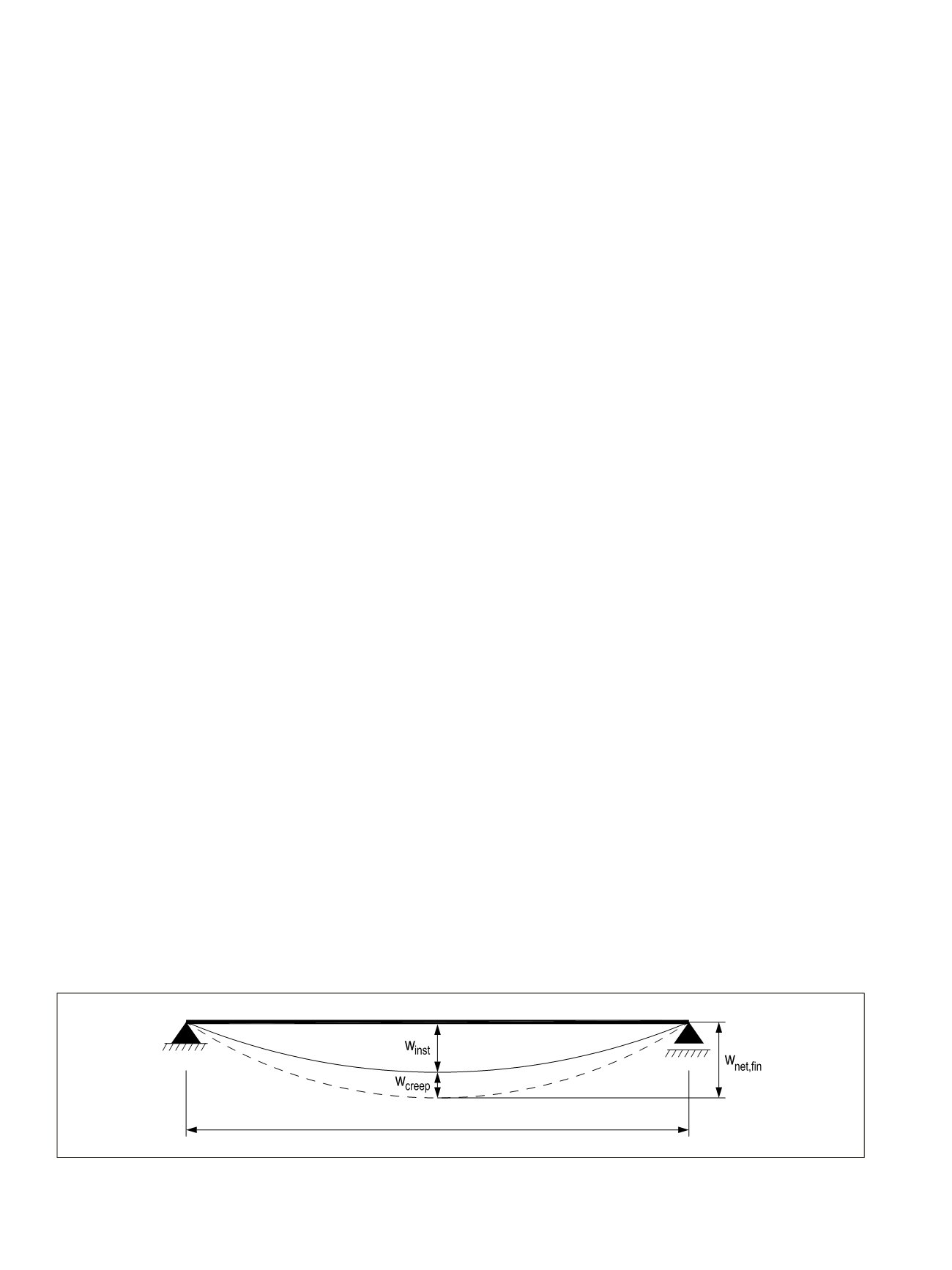
The components of deflection resulting from a combination
of actions are shown in Figure 4.27, where the symbols are de-
fined as follows:
−
w
inst
is the instantaneous deflection;
−
w
creep
is the creep deflection; and
−
w
fin
is the final deflection.
Note: LVL is not pre-cambered. Only in some very special cases
LVL beams may be cut to a camber by special sawing from an
LVL billet.
The net deflection below a straight line between the supports,
wnet,fin, should be taken as:
w
net,fin
=
w
inst
+
w
creep
(4.73)
Note: The recommended range of limiting values of deflections
for beams with span l is given in Table 4.10 depending upon the
level of deformation deemed to be acceptable. Information on
national limit values can be found in the National Annex for
Eurocode 5.
Figure 4.27
Components of deflection of LVL members.
fin
=
fin,G
+
fin,Q
1
+ ∑
fin,Q
1
(4.7
net, fin
=
inst
+
creep
=
5 ∙
d,i,SLS
∙
4
384 ∙
mean
∙
+
∙
d,i,SLS
∙
2
8 ∙
mean
∙
=
d,i,SLS
∙
3
48 ∙
mean
∙
+
∙
d,i,SLS
∙
2
4 ∙
mean
∙
136
LVL Handbook Europe