



 137 / 228

4. STRUCTURAL DESIGN OF LVL STRUCTURES
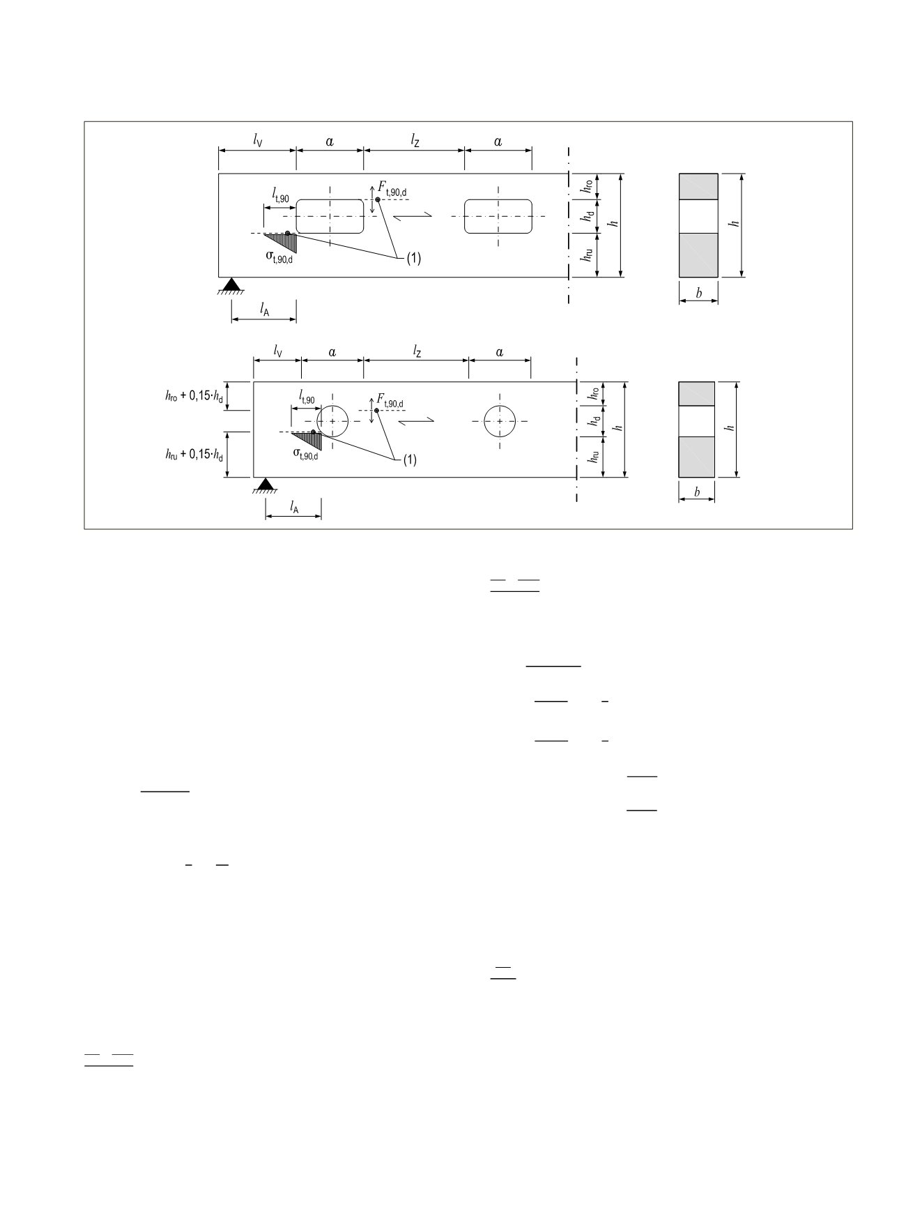
Figure 4.26.
Tension perpendicular to the grain stresses at the hole edges. (1) Risk of cracks due to the tension in perpendicular to grain
33
.
h
d
is the height of the hole for rectangular holes. For round
holes
h
d
= 0,7d may be used in the equation (4.59).
Load distribution length
l
t,90
is
l_(t,90)= {█(0,5∙(h_d+h
(4.61)
Verification of shear stress concentration at the hole edge shall
fulfil the condition:
τ_d=k_τ∙(1,5 ∙ V_d)/(b ∙ (h-h_d ) )≤f_(v,d)
(4.62)
Where
k_τ=1,85∙(1+a/h)∙(h_d/h)^0,2
(4.63)
τ
d
is the design value of shear stress;
k
τ
is the factor to determine maximum shear stress due to
stress concentration;
a
is the length of a hole [mm], for round holes a = hd; and
f
(v,d)
is the design value of edgewise shear strength
Bending stress at the location of a rectangular hole is verified
by the equations:
(M_d/W_n + M_(o,d)/W_o )/f_(m,d) ≤1
(4.64)
(M_d/W_n + M_(u,d)/W_u )/f_(m,d) ≤1
(4.65)
where
W_n=(b ∙ (h^2-h_d^2 ))/6
(4.66)
M_(o,d)=A_o/(A_u+A_o )∙V_d∙a/2
(4.67)
M_(u,d)=A_u/(A_u+A_o )∙V_d∙a/2
(4.68)
A_o=b∙h_ro and W_o=(b ∙ h_ro^2)/6
(4.69)
A_u=b∙h_ru and W_u=(b ∙ h_ru^2)/6
(4.70)
W
o
and
W
u
is the effective section modulus of the beam at
the location of a hole [mm
3
]
f
m,d
is the edgewise bending strength [N/mm
2
]
Bending stress at the location of a round hole is verified by the
equations:
(M_d/W_n )/f_(m,d) ≤1
(4.71)
The resistance of LVL-P beams at the location of holes maybe
improved and larger hole sizes are allowed when they are rein-
forced by gluing wood-based panels such as plywood to both
sides of the beam around the holes. Detailed design instruc-
tions are given e.g. in chapter F3.2 of the Austrian ÖNORM B
1995-1-1:2015
33
. As LVL beams are thin, internal reinforce-
ment with screws or glued-in-rods is not recommended.
t,90,d
=
d
∙ℎ
d
4∙ℎ
∙ �3 − �
ℎ
d
ℎ
�
2
� + 0,008 ∙
d
ℎ
r
(4.59)
ℎ
r
= �
min(ℎ
ro
; ℎ
ru
) for rectangular holes
min(ℎ
ro
+ 0,15 ∙ ; ℎ
ro
+ 0,15 ∙ ) for round holes
(4.60)
t,90
= � 0,5 ∙ (ℎ
d
+ ℎ) for rectangular holes
0,35 ∙ + 0,5 ∙ ℎ for round holes
(4.61)
d
=
τ
∙
1,5 ∙
d
∙ (ℎ−ℎ
d
)
≤
v,d
(4.62)
τ
= 1,85 ∙ �1 +
ℎ
� ∙ �
ℎ
d
ℎ
�
0,2
(4.63)
t,
,
d
∙
d
∙
∙
,
∙
(4.59)
ℎ
i
ro
;
l l
i
,
∙ ;
,
∙
l
.
t,
0,5 ∙ (ℎ
d
l l
,
∙
, ∙
l
(4.
∙
, ∙
∙
,
.
τ
,
∙
∙ �
ℎ ,
.63)
d n
+
o,d o m,d
≤ 1
(4.64)
d n
+
u,d u m,d
≤ 1
(4.65)
where
2 2
(4.66)
d n
+
o,d o m,d
≤ 1
d n
+
u,d u m,d
≤ 1
wh re
n
=
∙ �ℎ
2
−ℎ
d2
� 6
o,d
=
o u
+
o
∙
d
∙
2
u,d
=
u u
+
o
∙
d
∙
2
o
= ∙ ℎ
o
and
o
=
∙ ℎ
ro2
6
u
= ∙ ℎ
ru
and
u
=
∙ ℎ
ru2
6
d n m,d
≤ 1
d n
+
o,d o m,d
d n
u,d u m,d
≤ 1
w re
n
=
∙ �ℎ
2
ℎ
d2
� 6
o,d
=
o u o
∙
d
∙
2
u,d
=
u u
+
o
∙
d
∙
2
o
∙ ℎ
ro
and
o
=
∙ ℎ
ro2
6
u
= ∙ ℎ
ru
and
u
=
∙ ℎ
ru2
6
d n ,d
≤ 1
+
,
,
,
,
≤
,
o
,
d
∙ ℎ and
=
ru
d
2
,
d n
+
o,d o m,d
≤ 1
d n
+
u,d u m,d
≤ 1
where
n
=
∙ �ℎ
2
−ℎ
d2
� 6
o,d
=
o u
+
o
∙
d
∙
2
u,d
=
u u
+
o
∙
d
∙
2
o
= ∙ ℎ
ro
and
o
=
∙ ℎ
ro2
6
u
= ∙ ℎ
ru
and
u
=
∙ ℎ
ru2
6
d n m,d
≤ 1
d n
+
o,d o m,d
≤ 1
d n
+
u,d u m,d
≤ 1
where
n
=
∙ �ℎ
2
−ℎ
d2
� 6
o,d
=
o u
+
o
∙
d
∙
2
u,d
=
u u
+
o
∙
d
∙
2
o
= ∙ ℎ
ro
and
o
=
∙ ℎ
ro2
6
u
= ∙ ℎ
ru
and
u
=
∙ ℎ
ru2
6
d n m,d
≤ 1
d n
+
,d o m,d
≤ 1
d n
+
u,d u m,d
≤ 1
where
n
=
∙ �ℎ
2
−ℎ
d2
� 6
o,d
=
o u
+
o
∙
d
∙
2
u,d
=
u u
+
o
∙
d
∙
2
o
= ∙ ℎ
ro
and
o
=
∙ ℎ
ro2
6
u
= ∙ ℎ
ru
and
u
=
∙ ℎ
ru2
6
d n m,d
≤ 1
o,d
,d
d n
, u ,d
=
2 2
,
o
∙
,
=
=
2
r
6
,
Figure 4.26. Tension perpendicular to the grain stresses at the hole edges. (1) Risk of cracks
due to the tension in perpendicular to grain
33
.
(Kuva_97_2 f t90 in rectangular hole,
Kuva_97_3 f t 90 in round hole)
The tension perpendicular to the grain force
F
t,90,d
depends on the shear force
V
d
and
bending moment
M
d
at the edge of the hole:
t,90,d
=
d
∙ℎ
d
4∙ℎ
∙ [3 − (
ℎ
d
ℎ
)
2
] + 0,008 ∙
d
ℎ
r
(4.59)
where
ℎ
r
= {
min(ℎ
ro
; ℎ
ru
) for rectangular holes
min(ℎ
ro
+ 0,15 ∙ ; ℎ
ro
+ 0,15 ∙ ) for round holes
(4.60)
is the heig t of the hol for rectangular h les. For round holes
h
d
= 0,7
d
may be
use in the quatio (4.59).
Load distribution length
l
t,90
is
t,90
= { 0,5 ∙ (ℎ
d
+ ℎ) for rectangular holes
0,35 ∙ + 0,5 ∙ ℎ for round holes
(4.61)
erificati of shear stress concentration at the hole edge shall fulfil the condition:
d
=
τ
∙
1,5 ∙
d
∙ (ℎ−ℎ
d
)
≤
v,d
(4.62)
Where
τ
= 1,85 ∙ (1 +
ℎ
) ∙ (
ℎ
d
ℎ
)
0,2
(4.63)
is the design value of shear stress;
τ
is the fact r to determine maximum shear stress due to stress concentration;
LVL Handbook Europe
135