



 133 / 228

4. STRUCTURAL DESIGN OF LVL STRUCTURES
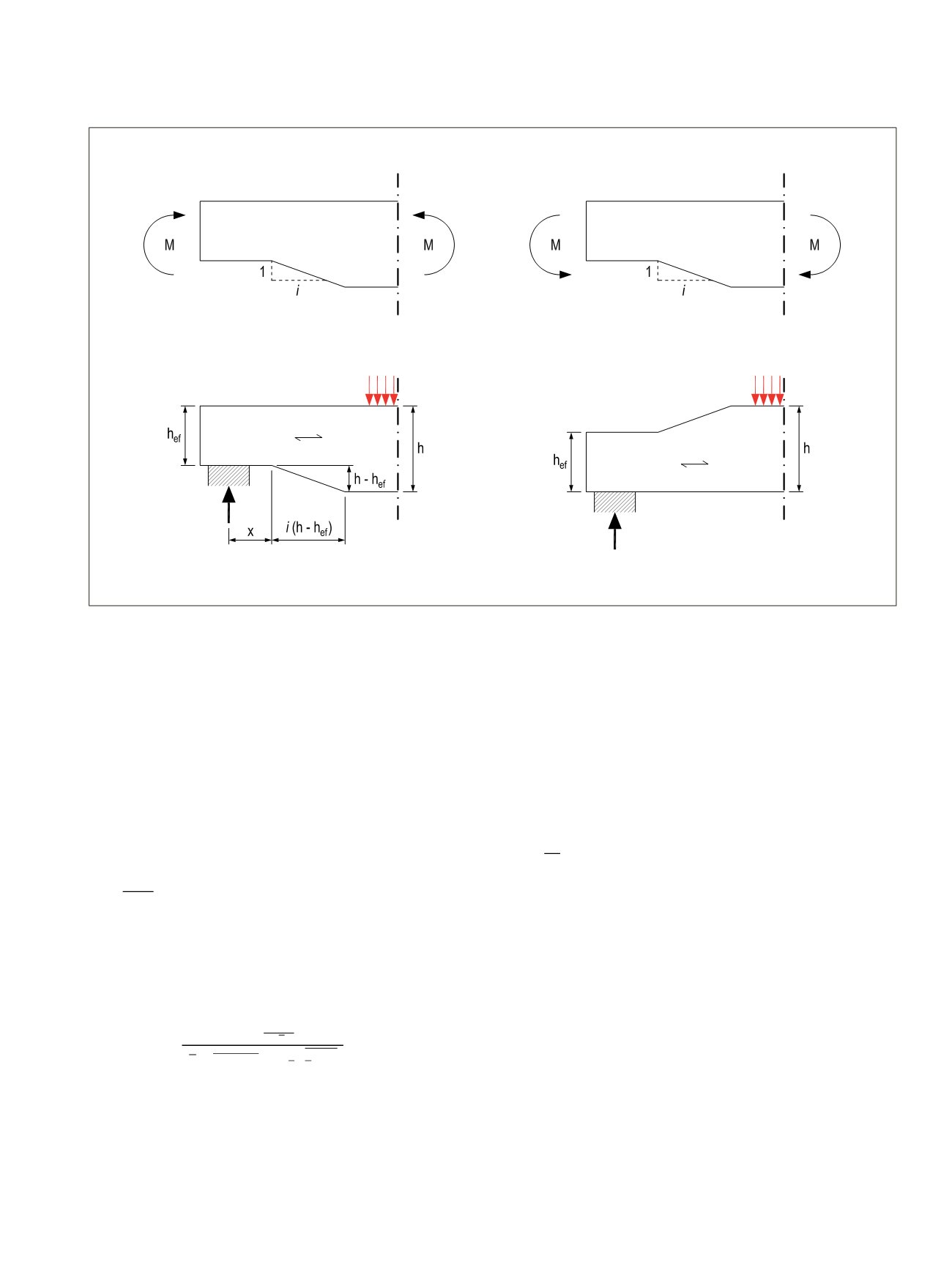
Figure 4.20.
Bending at a notch A) with tensile stresses at the notch B) with compressive stresses at the notch (EC5 Figure 6.10 and 6.11).
When the taper at the notch at tensile side is steeper than 1:10,
it can be located only at the support.
For beams with rectangular cross sections and where the
grain runs essentially parallel to the length of the member, the
shear stresses at the notched support should be calculated us-
ing the effective (reduced) depth hef, see Figure 4.18 b).
It should be verified that
τ_d=(1,5 V_d)/(b ∙ h_ef )≤k_v∙f_(v,d)
(4.46) (EC5 6.60)
where kv is a reduction factor defined as follows:
− For beams notched at the opposite side to the support, see
Figure 4.20 b), kv = 1,0.
− For beams notched on the same side as the support, see Fig-
ure 4.18 a)
k_v=min(1 ; (k_n (1 + (1,1 i^1,5)/√h)
(4.47) (EC5 6.62)
where
i
is the notch inclination, see Figure 4.20 a);
h
is the beam depth in mm;
x
is the distance from line of action of the support reaction to
the corner of the notch, in mm; and
α=h_ef/h
(4.48)
k
n
is 4,5 for LVL in general. Note: manufacturers provide
product-specific information on the
k
n
values of their products,
especially where the advantages LVL-C are evident.
d
=
1,5
d
∙ ℎ
ef
≤
v
∙
v,d
(4.46) (EC5 6.60)
v
= min�1 ;
n
�1 +
1,1 1, √ℎ
�
√ℎ �� (1 − ) + 0,8
ℎ
�
1
−
2
�
�
(4.47) (EC5 6.62)
ℎ
ef
(4.48)
d
=
1,5
d
∙ ℎ
ef
≤
v
∙
v,d
(4.46) ( 5 6.60)
v
in 1 ;
n
�1 +
1,1 1,5 √ℎ
�
√ℎ �� (1 − ) + 0,8
ℎ
�
1
−
2
�
(4.47) ( 5 6.62)
ℎ
ef
ℎ
(4.48)
d
=
1,5
d
∙ ℎ
ef
≤
v
∙
v,d
v
= min�1 ;
n
�1 +
1,1 1,5 √ℎ
�
√ℎ �� (1 − ) + 0,8
ℎ
�
1
−
2
�
�
=
ℎ
ef
ℎ
A
B
LVL Handbook Europe
131