



 131 / 228

4. STRUCTURAL DESIGN OF LVL STRUCTURES
0,0
0,1
0,2
0,3
0,4
0,5
0,6
0,7
0,8
0,9
1,0
0
25 50 75 100 125 150 175 200 225 250
Buckling factor k
C
Slendernes ratio λ
Buckling factor k
c
for LVL
LVL 32 P
LVL 48 P
LVL 36 C
LVL 25 C
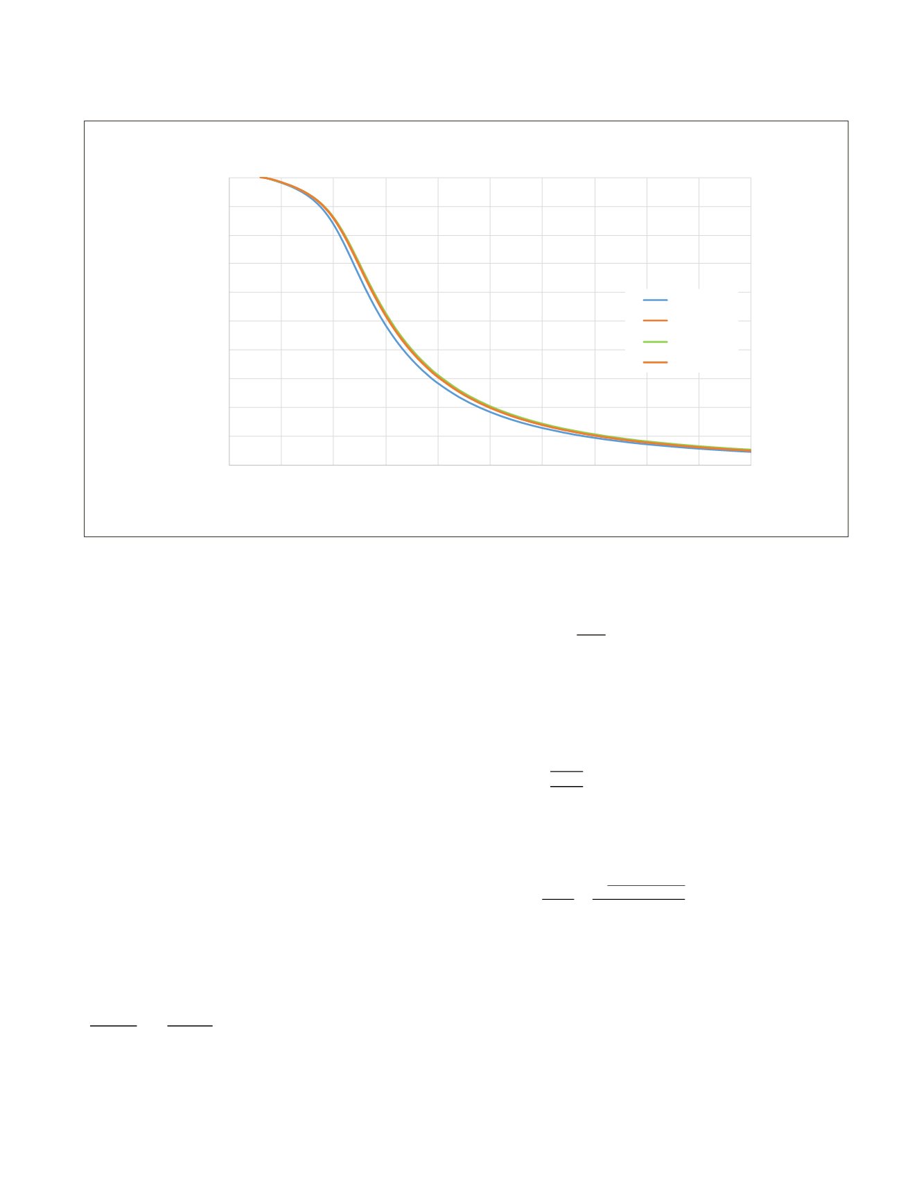
Figure 4.18.
Buckling coefficient
k
c
of different LVL classes for different slenderness ratios
λ
.
4.3.9.3 Beams subjected to either bending or
combined bending and compression– Lateral
torsional buckling (LTB)
Lateral torsional stability shall be verified both in the case
where only a moment
M
y
exists about the strong axis
y
and
where a combination of moment
M
y
and compressive force
N
c
exists.
In the case where a bending moment M exists only on one
axis, the stresses should satisfy the following expression:
σ_(m,d) ≤ k_crit ∙f_(m,d)
(4.38) (EC5 6.33)
where
σ
m,d
is the design bending stress;
f
m,d
is the design bending strength; and
k
crit
is a factor that takes into account the reduced bending
strength due to lateral buckling.
In the case where a combination of moment
M
y
about the
strong axis
y
and compressive force
N
c
exists, the stresses
should satisfy the following expression
(σ_(m,d)/(k_crit f_(m,d) ))^2+σ_(c,0,d) (4.39) (EC5 6.35)
For beams with an initial lateral deviation from straightness
within the limits defined in Section 10 of Eurocode 5,
k
crit
may
be determined from expression:
k_crit={█(1,when
(4.40) (EC5 6.34)
The factor
k
crit
may be taken as 1,0 for a beamwhere lateral dis-
placement of its compressive edge is prevented throughout its
length and where torsional rotation is prevented at its supports
The relative slenderness for bending should be taken as
λ_(rel,m)=√(f_(m,k)/σ_(m,crit) )
(4.41) (EC5 6.30)
where
σ
m,crit
is the critical bending stress calculated according
to the classical theory of stability, using 5-percentile stiffness
values. The critical bending stress should be taken as:
σ_(m,crit)=M_(y,crit)/W_y =(π√(E_
(4.42) (EC5 6.31)
where
E
0,05
is the fifth percentile value of modulus of elasticity
parallel to grain;
G
0,05
is the fifth percentile value of shear modulus parallel to
grain; Note:
G
edge,0,05
of LVL shall be used;
I
z
is the second moment of area about the weak axis
z
;
I
tor
is the torsional moment of inertia;
l
ef
is the effective length of the beam, depending on the
support conditions and the load configuration,
according to Table 4.9;
W
y
is the section modulus about the strong axis
y
.
m,d
≤
crit
∙
m,d
(4.38) (EC5 6.33)
�
,d crit
m,d
�
2
+
c,0,d c,z
c,0,d
≤ 1
(4.39) (EC5 6.35)
crit
= �
1, when
rel,m
≤ 0,75
1,56 − 0,75
rel,m
, when 0,75 <
rel,m
≤ 1,4
1
rel,m2
, when 1,4 <
rel,m
(4.40) (EC5 6.34)
m,d
≤
crit
∙
m,d
(4.38) (EC5 6.33)
�
m,d crit
m,d
�
2
+
c,0,d c,z
c,0,d
≤ 1
(4.39) (EC5 6.35)
crit
= �
1, when
rel,m
≤ 0,75
1,56 − 0,75
rel,m
, when 0,75 <
rel,m
≤ 1,4
1
rel,m2
, when 1,4 <
rel,m
(4.40) (EC5 6.34)
m,d
≤
crit
∙
m,d
�
m,d crit
m,d
�
2
+
c,0,d c,z
c,0,d
≤ 1
crit
= �
1, when
rel,m
≤ 0,75
1,56 − 0,75
rel,m
, when 0,75 <
rel,m
≤ 1,4
1
rel,m2
, when 1,4 <
rel,m
rel,m
= �
m,k m,crit
m,crit
=
y,crit y
=
�
0,05 0,05 tor
ef
y
tor
=
1
∙ ℎ ∙
3
m,d
≤
crit
∙
m,d
�
m,d crit
m,d
�
2
+
c,0,d c,z
c,0,d
≤ 1
crit
= �
1, when
rel,m
≤ 0,75
1,56 − 0,75
rel,m
, when 0,75 <
rel,m
≤ 1,4
1
rel,m2
, when 1,4 <
rel,m
rel,m
= �
,k m,crit
m,crit
=
y,crit y
=
�
0,05 0,05 tor
ef
y
tor
=
1
∙ ℎ ∙
3
f
m,d
is the design bending strength;
k
crit
is a factor that takes into account the reduced bendin
buckling.
In the case where a combination of moment
M
y
about the strong a
force
N
c
exists, the stresses should satisfy the following expressio
(
m,d crit
m,d
)
2
+
c,0,d c,z
c,0,d
≤ 1
For beams with an initial lateral deviation from straightness within
Section 10 of Eurocode 5,
k
crit
may be determined from expression
crit
= { 1 when
rel,m
≤ 0,75
1,56 − 0,75
rel,m
when 0,75 <
rel,m
≤ 1,4
1
rel,m2
hen 1,4 <
rel,m
The factor
k
crit
may be taken as 1,0 for a beam where lateral displa
edge is prevented throughout its length and where torsional rotati
supports
The relative slenderness f r be ding should be taken as
rel,m
= √
m,k m,crit
where
σ
m,crit
is the critical bending stress calculated according to th
stability, using 5-percentile stiffness values. The critical bending st
m,crit
=
y,crit y
=
√
0,05 0,05 tor
ef
y
where
E
0,05
is the fifth percentile value of modulus of elasticity pa
G
0,05
is the fifth percentile value of shear modulus parallel
LVL shall be used;
I
z
is the second moment of area about th weak axis
z;
I
tor
is the torsional moment of in rtia;
l
ef
is the effective length f he beam, depending on the
load configuration, according to Table 4.9;
W
y
is th section modulus about the strong axis
y.
In the case of rectangular cross sections:
tor
=
1
∙ ℎ ∙
3
where
LVL Handbook Europe
129