



 127 / 228

4. STRUCTURAL DESIGN OF LVL STRUCTURES
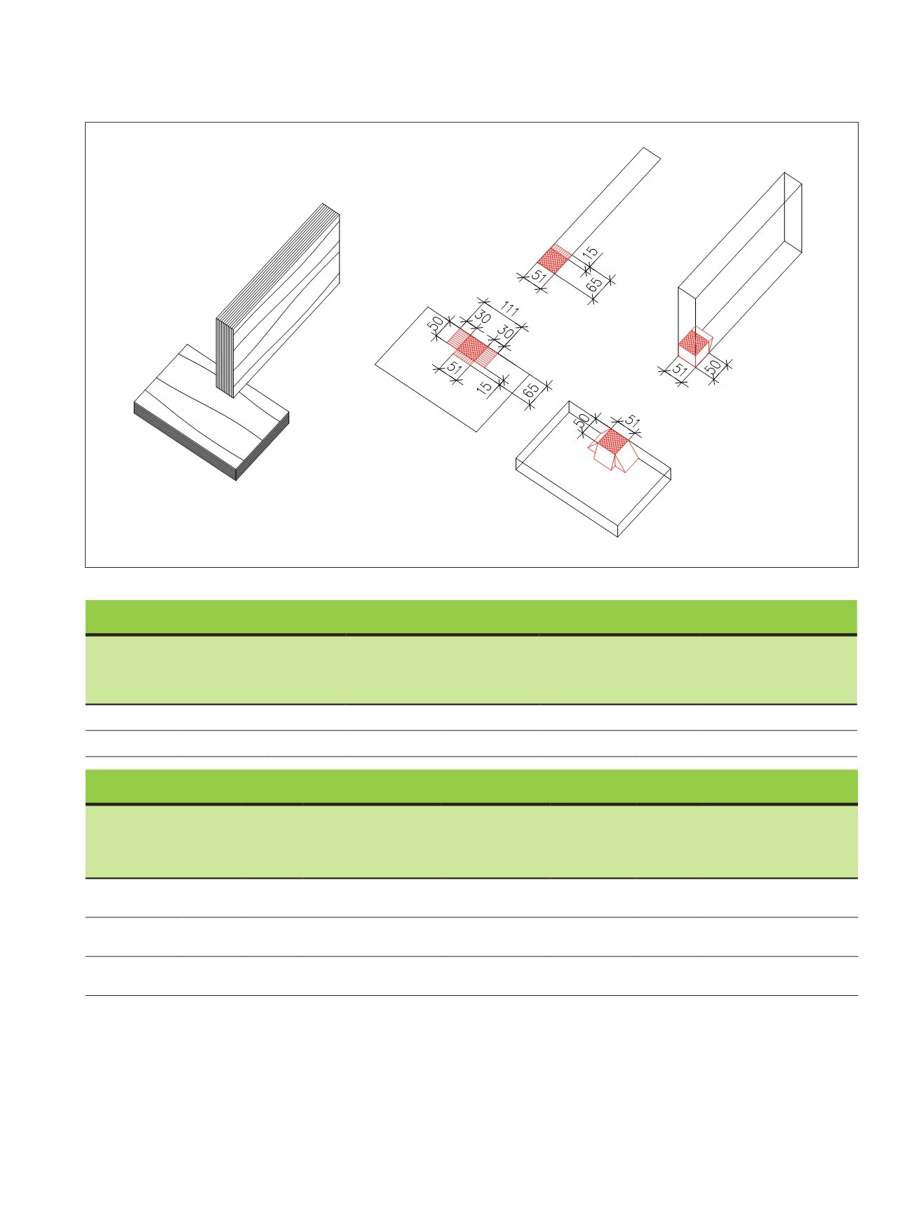
Figure 4.14.
Example of an LVL beam supported on an LVL sole plate. Effective contact area is increased by 15 mm in the edgewise direction
on the beam and separately by 60 mm (2x30 mm) in the length direction and 15mm in width direction on the sole plate.
LVL 04, Figure 4.13
LVL beam
Product
type
Beam
thickness
b
[mm]
Support
length
l
[mm]
Increase in
actual contact
length
l
1
[mm]
Effective
contact area
A
ef
=
b
∙(
l
+
l
1
)
[mm2]
Compression
strength
f
c,90,edge,k
[N/mm2]
k
c,90
[-]
Characteristic bearing
capacity
F
c,k
=
A
ef
∙
k
c,90
∙
f
c,90,edge,k
[kN]
LVL 48 P
51
50
15
3 315
6,0
1,0
20
LVL 36 C
51
50
15
3 315
9,0
1,0
30
LVL or solid wood sole plate
Product
type
Contact
width
b
[mm]
Contact
length
l
[mm]
Increase in actual
contact length parallel
l
1
and perpendicular
l
2
[mm]
Effective contact
area
A
ef
=
b
∙(
l
+
l
1
) + (
b
∙
l
2
)
[mm2]
Compression
strength
f
c,90,edge,k
[N/mm2]
k
c,90
[-]
Characteristic bearing
capacity
F
c,k
=
A
ef
∙
k
c,90
∙
f
c,90,edge,k
[kN]
LVL 48 P or
36 C
50
51
l
1
=30,
l
2
=15
6 315
2,2
1,4
19,5
LVL 48 P or
36 C of pine
50
51
l
1
=30,
l
2
=15
6 315
3,3
1,4
29
C24 solid
wood
50
51
l
1
=30,
l
2
=0
5 550
2,5
1,25
17,3
LVL Handbook Europe
125