



 123 / 228

4. STRUCTURAL DESIGN OF LVL STRUCTURES
4.3.2 Shear
For shear with a stress component parallel to the grain, see
Figure 4.5(a, b, d and e), and for shear with both stress compo-
nents perpendicular to the grain, see Figure 4.4(c and f), the
following expression shall be satisfied:
τ
d
≤
f
v,d
(4.7) (EC5 6.13)
where
τ
d
is the design shear stress;
f
v,d
is the design shear strength for the actual condition.
LVL is not sensitive to cracking and therefore the factor
k
cr
=1,0. This means that the full member width b can be used in
equation (4.8) of an effective width bef of the member in the
verification of shear resistance of members in bending.
b
ef
=
k
cr
∙
b
(4.8) (EC5 6.13a)
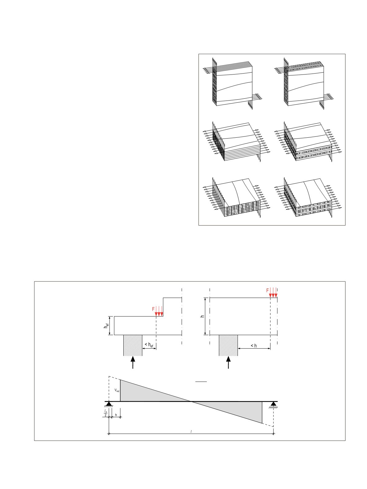
At supports, the contribution to the total shear force of
a concentrated load F acting on the top side of the beam and
within a distance h or hef from the edge of the support may
be disregarded, see Figure 4.5. For beams with a notch at the
support this reduction in the shear force applies only when
the notch is on the opposite side to the support. For uniformly
distributed loads, the determining shear force maybe taken at
a distance of the member height
h
from the support.
Figure 4.5.
A) LVL-P shear stress edgewise parallel to grain
B) LVL-P shear stress flatwise parallel to grain C) LVL-P shear stress
flatwise perpendicular to grain (rolling shear) D) LVL-C shear stress
edgewise parallel to grain E) LVL-C shear stress flatwise parallel to
grain (rolling shear of cross veneers) F) LVL-C shear stress flatwise
perpendicular to grain (rolling shear of parallel veneers).
2 1
A
red
h
V V
l
l
Figure 4.6.
Conditions at a support, for which the concentrated force F may be disregarded in the calculation of the shear force. In the case of
uniformly distributed loads, the shear force maybe reduced to the value which it has at a distance of the member height h from a support
31
.
d
≤
v, d
(4.7) (EC5 6.13)
ef
=
cr ∙
(4.8) (EC5 6.13a)
d
≤
v, d
(4.7) (EC5 6.13)
ef
=
cr ∙
(4.8) (EC5 6.13a)
D
E
B
C
F
A
LVL Handbook Europe
121