



 142 / 228

4.4.2 Beams and columns
When LVL-P or LVL-C members are glued together in the
same direction as rectangular GLVL cross sections, the ma-
terial values of the LVL lamina may be used. Additionally, the
size effect shall be taken into account for the shear strength
and bending strength flatwise to the LVL lamellas. The size ef-
fect parameters are declared in manufacturers’ technical doc-
umentation.
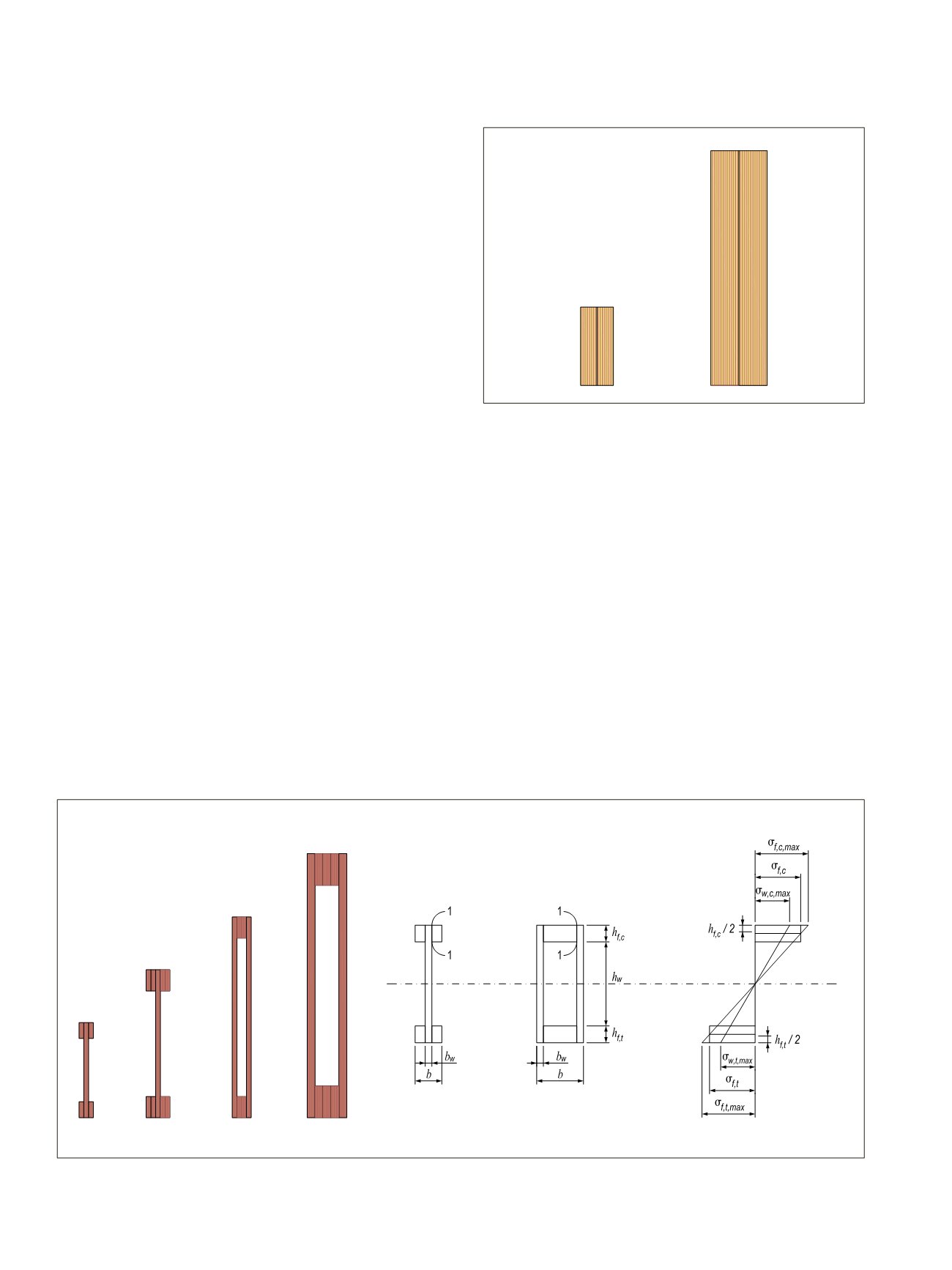
LVL I-beams and box beams have LVL-P flanges and
LVL-C webs which keep the beams straight and stable in
changing moisture conditions. Glued thin-webbed I-beam and
box beam specific design instructions are given in Eurocode 5
clause 9.1.1. For the flanges it shall be verified that:
• Axial tension stress
σ
f,t,max
at the extreme fibre of the flange
edge does not exceed the bending strength fm,d of the flange
material
• Axial tension stress
σ
f,t,d
at the centre of the flange does not
exceed the tension strength
f
t,0,d
of the material
• Axial compression stress
σ
f,c,max
at the extreme fibre of the
flange edge does not exceed the bending strength
f
m,d
of the
flange material
• Axial compression stress
σ
f,c,d
at the centre of the flange does
not exceed the compression strength
f
c,0,d
of the material tak-
ing into consideration lateral instability
For the web material it shall be verified that:
• Compressive and tension stresses
σ
w,c,max
and
σ
w,t,max
do not
exceed the respective strengths
f
w,t,0,d
and
f
w,c,0,d
of the web
material
• Design shear force acting on the web
F
v,w,Ed
does not exceed
the shear capacity
R
v,w,d
of the beam taking into considera-
tion buckling as a plate
4. STRUCTURAL DESIGN OF LVL STRUCTURES
Figure 4.30.
Multiple-glued GLVL beams.
For glued joints between web(s) and flanges (section 1-1
in Figure 4.31), it should be verified by equation (9.10) of Eu-
rocode 5 that the shear stress
τ
mean,d
does not exceed the planar
shear strength of the flange or web materials.
In SLS design, bending and shear deformations are taken
into account. For simplicity, the shear rigidity GAmay be eval-
uated based on the webs only.
LVL I-beam and box beam suppliers also have more ad-
vanced design instructions tailored and approved for their ele-
ments as part of their technical documentation.
Figure 4.31.
GLVL I-beams, box beams and stress distribution in the cross section. Section 1-1 is glued joint between web and flange.
140
LVL Handbook Europe