



 90 / 228

2. LVL STRUCTURES IN FLOORS, WALLS, ROOFS AND IN SPECIAL APPLICATIONS
Calculations according to
EN 1995-1-1:2004+A1:2008 and its
Finnish National Annex. Permanent
load is 25% of the total characteristic
load, the rest is snow load. Wind load
not accounted for. Service class 1 or
2; consequences class CC2. The beam
has lateral torsional buckling (LTB)
supports on the top surface at
≤ 600 mm spacing. Double beams are
analysed as separate beams for LTB.
The support length is to be calculated
separately. Net final deflection
w
net,fin
≤ L/300.
γ
M
= 1,2 Note: Glass
openings may require a more strict
deflection limit.
Does not replace project-specific
structural design.
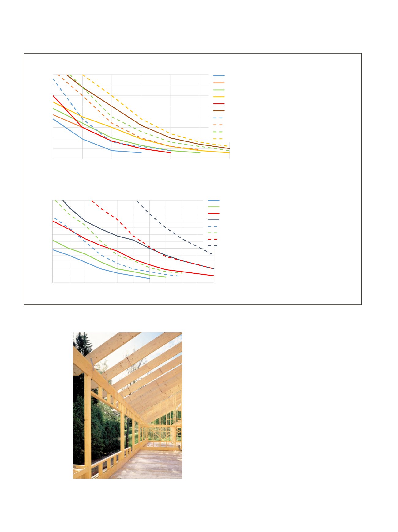
Figure 2.62.
Capacities [kN/m] of single-span LVL 48 P lintel beams for predesign.
2.4.4 Integrated rim beams
Integrated rimbeams of timber frame walls are an essential and
common application for LVL-P in Europe. They are installed
on top of notched wall studs and carry the loads from the roof
or other structures above to the studs. Since the integrated rim
beams transfer the loads, the floor joist, roof rafter or roof truss
spacing can be independent of the wall stud locations. Inte-
grated rim beams simplify the structure so that separate lin-
tels are not required except for the largest openings. In off-site
production integrated rim beams are installed integrally in the
wall elements.
As LVL is available in long lengths, builders often use the
dimensionally accurate and straight LVL-P members to align
and brace the wall frame when they are assembled and to en-
sure that the overall dimensions of the building are correct.
Similar to lintels, LVL integrated rim beams improve the build-
ing physics detailing by reducing cold bridging compared to
massive beams, as there is more space for thermal insulation.
LVL integrated rim beams are typically 45-51 mm thick and
200-300 mm high.
Metsä Wood
Figure 2.63.
Integrated rim beam in timber
frame wall structure.
2,5
3,0
3,5
4,0
4,5
5,0
5,5
6,0
6,5
7,0
7,5
8,0
Span length [m]
Floor main beams
0
5
10
15
20
25
30
35
40
45
50
55
60
2,0 2,5 3,0 3,5 4,0 4,5 5,0 5,5 6,0 6,5 7,0
Characterastic load [kN/m]
Maximum span length [m]
LVL 48 P lintel beams h = 360 - 600mm
45x360
51x400
63x500
75x600
2x45x360
2x51x400
2x63x500
2x75x600
0
5
10
15
20
25
30
35
40
1,5
2,0
2,5
3,0
3,5
4,0
4,5
Characterastic load [kN/m]
Maximum span length [m]
LVL 48 P lintel beams h = 200 - 300mm
45x200
45x240
45x260
45x300
75x200
75x300
2x45x200
2x45x240
2x45x260
2x45x300
0
10
20
30
40
50
60
70
80
90
1,5
2,0
2,5
3,0
3,5
4,0
4,5
5,0
5,5
6,0
6,5
7,0
7,5
8,0
Characteristic load [kN/m]
Span length [m]
Floor main beams
45x200 45x240 45x260 45x300 45x360 51x400 63x500 75x200 75x300 75x600
0
5
10
15
20
2,0 2,5 3,0 3,5 4,0 4,5 5,0 5,5 6,0 6,5 7,0
Charactera
Maximum span length [m]
0
5
10
15
20
25
30
35
40
1,5
2,0
2,5
3,0
3,5
4,0
4,5
Characterastic load [kN/m]
Maximum span length [m]
LVL 48 P lintel beams h = 200 - 300mm
45x200
45x240
45x260
45x300
75x200
75x300
2x45x200
2x45x240
2x45x260
2x45x300
88
LVL Handbook Europe