



 168 / 228

6. PERFORMANCE OF LVL IN FIRE
6.5 FIRE RESISTANCE DESIGN OF FLOOR
&WALL STRUCTURES WITH CAVITIES
The fire resistance of LVL wall and floor assemblies can be cal-
culated according to Annexes C and D of EN1995-1-2 and
its National Annexes. When the cavities between the joists or
studs are filled with rock fibre insulation, Annex C shall be
used. For void cavities Annex D shall be used.
In the case of filled cavities, the design process according to
EN1995-1-2 Annex C is the following:
1. Verification that the structure fulfils the boundary condi-
tions of the design method, note that it is valid for max 60
min fire resistance.
2. Protection time tch for the start of charring and tf for failure
of the panels are evaluated for the protection panel combi-
nation based on the equations in Annex C, and technical
specifications of the panel suppliers. It is essential to use de-
tailing that keeps the protective rock fibre insulation in place
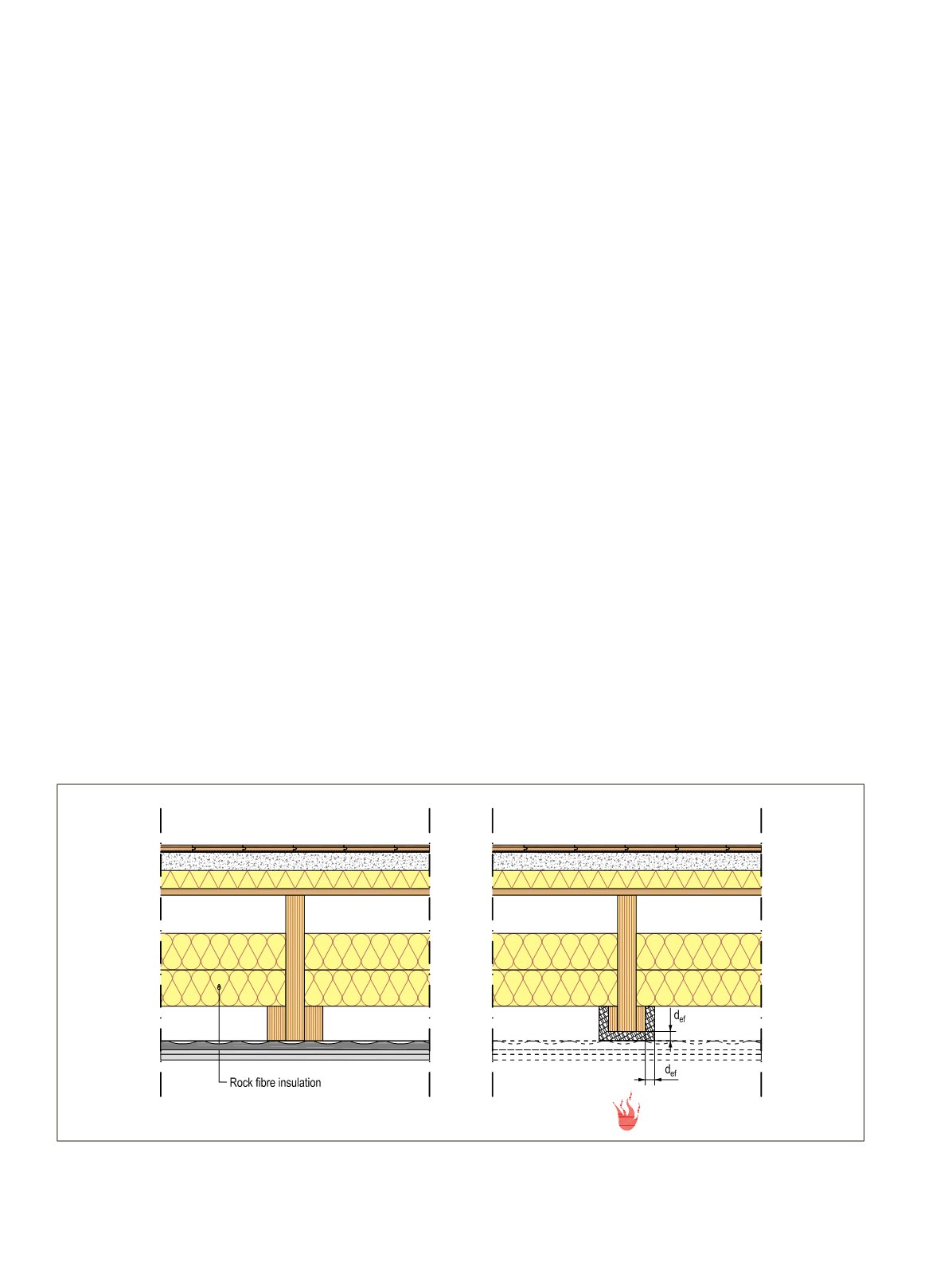
also after failure of the protection panels. One example for
floor structure is fixing wooden battens to the joists to create
a shelf to support the insulation, see Figure 6.11.
3. Residual cross section of the studs or joist is calculated with
the assumption that they char only from the edge of the fire
exposed side. Notional charring rate is calculated with ad-
justment factors which depend on the phase of the charring
and the thickness of the joist or stud.
4. The resistance of the residual cross section is calculated with
strength values fd,fi, see equation (6.2). The reduction fac-
tor kmod,fi values are defined in section C.3 of the Annex
C. The reduction depends on the member depth and the
notional charring depth and the
k
mod,fi
has a significant
influence on the resistance. In the case of wall structures, the
same value of kmod,fi may be used both in the width and in
the thickness direction of a stud.
In the case of void cavities, the design process according to
EN1995-1-2 Annex D is the following:
1. Protection time tch for the start of charring and tf for failure
of the panels are evaluated for the protection panel combi-
nation based on the equations in Annex D, and technical
specifications of the panel suppliers.
2. Residual cross section of the studs or joist is calculated with
the assumption that they are charring from the sides and
the edge of the fire exposed side. Charring depth is calcu-
lated with adjustment factors which depend on the phase
of the charring, similarly to beams and columns that are
initially protected from fire exposure in subsection 3.4.3.2.
of EN1995-1-2.
3. The resistance is calculated for an effective cross section ac-
cording to subsection 4.2.2 of EN1995-1-2 with strength
values
f
d,fi
, see equation (6.2).
The resistance to fire of an LVL joist floor is mainly dependent
on the properties of the protective panels. Since the thickness
of LVL joists is usually 45–57 mm, their resistance reduces rap-
idly when their sides are exposed to fire.
Fire resistance of rib slabs and box slabs may be calculat-
ed with the same principles, but manufacturer-specific design
instructions according to their ETAs shall be followed for, e.g.,
the conditions when the structural gluing may be utilized.
Figure 6.11.
LVL joist floor structure with rock fibre filled cavities. Wooden battens fixed to the joists create a shelf that keeps the rock fibre
insulation in place protecting the sides of the joists from charring.
166
LVL Handbook Europe