



 165 / 228

the resistance of LVL structures in demanding cases using, e.g.,
performance-based design methods.
Note: For special cases where more advanced design methods are
used, the report VTT-S-04746-16 also has information on the
charring rate β0 in a test based on to a more stringent hydrocar-
bon (HC) time-temperature exposure curve (EN 1363-2:1999).
6.4.3 Design of unprotected beams and
panels
Since LVL beams are typically slender structures with larg-
est available beam thicknesses up to 75 mm without multi-
ple gluing, unprotected LVL beams cannot be designed for
higher than 15 min fire resistance time requirements. The ze-
ro strength layer (
k
0
∙
d
0
) reduces the thickness of an effective
cross section significantly, making the beam evenmore slender
in lateral torsional buckling analysis.
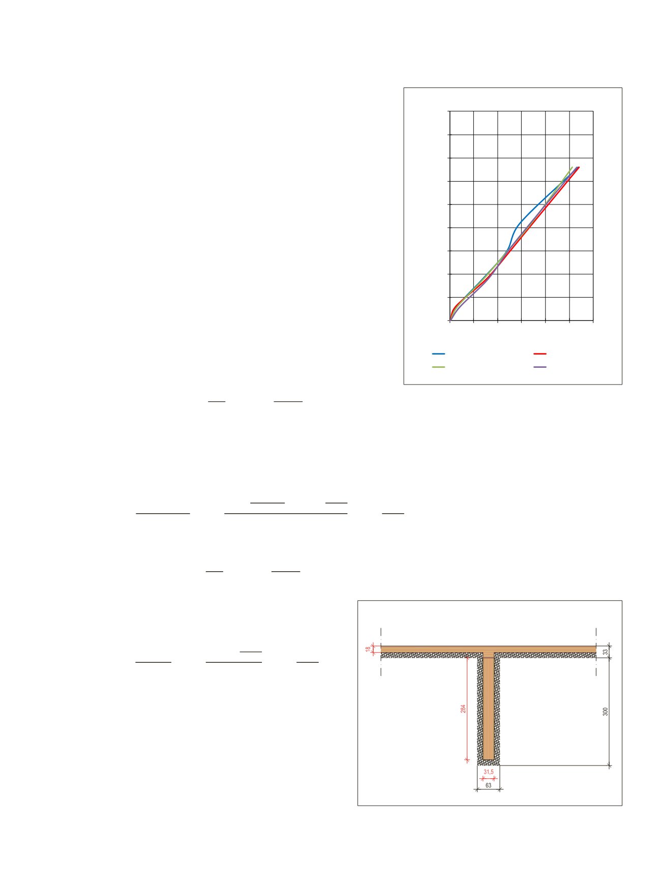
Example: 63x300 mm LVL-P beam and 33 mm LVL-C panel
in 15 minute fire exposure:
Beam:
d_(ef,beam)=β_n∙t+k_0∙d_0=0,70 mm/
min∙15min+15min/20min∙7mm=15,75mm
Size of effective cross section of the beam in 3-side fire expo-
sure:
Width
b
:
63 mm - 2∙15,75 mm =31,5 mm
Height
h
:
300 mm - 15,75 mm = 284 mm
Design value of bending strength for LVL 48 P:
f_(m,d,fi)=k_(mod,fi)∙(k_fi∙〖k_h∙f〗_(m,k))/γ_(M,fi)
=1,0∙(1,1∙(300mm/284mm)^0,15∙44 N/mm^2 )/1,
6. PERFORMANCE OF LVL IN FIRE
Figure 6.7.
One-dimensional charring
of LVL-C is linear in a 120 minutes
fire exposure test according to the
standardized time-temperature curve.
Blue and red curves: exposure on the wide
face of the specimens. Green and grey
curves: exposure on the edge face of the
specimens
39
.
0
10
20
30
40
50
60
70
80
90
0 20 40 60 80 100 120
CHARRING DEPTH [mm]
TIME [min]
Wide face 2
Wide face 1
Edge face 1
Edge face 1
Figure 6.8.
Effective cross section after 15 min fire exposure.
m,d,fi
=
mod,fi
∙
fi
∙
h
∙
m,k M,fi
= 1,0 ∙ 1,1 ∙ � 300mm 284mm �
0,15
∙ 44 Nmm
2
1,0
= 44,3 Nmm
2
ef,panel
=
0
∙ +
0
∙
0
= 0,65 mmmin ∙ 15min + 15min 20min ∙ 7mm = 15 mm
m,d,fi
=
mod,fi
∙
fi
∙
m,k M,fi
= 1,0 ∙ 1,1 ∙ 36 Nmm
2
1,0 = 39,6 Nmm
2
Figure 6.7. One-dim nsional charring of LVL-C is linear in a 120 minute fire exposure test
according to th standa dized time-temperature curve. Blue and red curves: exposure on the
wide face of the specimens. Green and grey curves: exposure on the edge face of the
specimens
39
.
Note: For special cases where more advanced design methods are used, the report VTT-S-
04746-16 also has information on the charring rate
β
0
in a test based on to a more stringent
hydrocarbon (HC) time-temperature exposure curve (EN 1363-2:1999).
6.4.3
Design of unprot cted beams an pa ls
Since LVL beams are typically slender structures with largest available beam thicknesses up
to 75 mm without multiple gluing, unprotected LVL beams cannot be designed for higher than
15 min fire resistance time requirements. The zero strength layer (
k
0
∙ d
0
)
reduces the
thickness of an effective cross section significantly, making the beam even more slender in
lateral torsional buckling analysis.
Example: 63x300 mm LVL-P beam and 33 mm LVL-C panel in 15 minute fire exposure:
Beam:
ef,beam
=
n
∙ +
0
∙
0
= 0,70 mmmin ∙ 15min + 15min 20min ∙ 7mm = 15,75mm
Size of effective cross section of the beam in 3-side fire exposure:
Width
b
:
63 mm - 2∙15,75 mm = 31,5 mm
Height
h
:
300 mm - 15,75 mm = 284 mm
Design value of bending strength for LVL 48 P:
m,d,fi
=
mod,fi
∙
fi
∙
h
∙
m,k M,fi
= 1,0 ∙ 1,1 ∙ ( 300mm 284mm )
0,15
∙ 44 Nmm
2
1,0
= 44,3 Nmm
2
Panel:
Panel:
d _ ( e f , p a n e l ) = β _ 0 ∙ t + k _ 0 ∙ d _ 0 = 0 , 6 5
mm /
min∙15min+15min/20min∙7mm=15 mm
Effective thickness of the panel
t
panel
: 33 mm - 15 mm = 18 mm
Design value of bending strength for LVL 36 C:
f_(m,d,fi)=k_(mod,fi)∙(k_fi∙f_(m,k))/γ_(M,fi) =1,0∙(1,1∙36 N/
mm^2 )/1,0=39,6 N/mm^2
m,d,fi
=
mod,fi
∙
fi
∙
h
∙
m,k M,fi
= 1,0 ∙ 1,1 ∙ � 300mm 284mm �
0,15
∙ 44 Nmm
2
1,0
= 44,3 Nmm
2
ef,panel
=
0
∙ +
0
∙
0
= 0,65 mmmin ∙ 15min + 15min 20min ∙ 7mm = 15 mm
m,d,fi
=
mod,fi
∙
fi
∙
m,k M,fi
= 1,0 ∙ 1,1 ∙ 36 Nmm
2
1,0 = 39,6 Nmm
2
m,d,fi
=
mod,fi
∙
fi
∙
h
∙
m,k M,fi
= 1,0 ∙ 1,1 ∙ � 300mm 284mm �
0,15
∙ 44 Nmm
2
1,0
= 44,3 Nmm
2
ef,panel
=
0
∙ +
0
∙
0
= 0,65 mmin ∙ 15min + 15 i
20min ∙ 7mm = 15 mm
m,d,fi
=
mod,fi
∙
fi
∙
m,k M,fi
= 1,0 ∙ 1,1 ∙ 36 Nmm
2
1,0 = 39,6 Nmm
2
LVL Handbook Europe
163