



 163 / 228

6. PERFORMANCE OF LVL IN FIRE
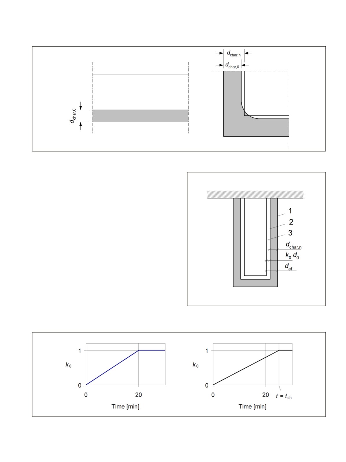
Figure 6.4.
Left: One-dimensional charring of panel or wide cross section when fire exposure is below on one side, Right: Charring depth
d
char,0
for one-dimensional charring and notional charring depth
d
char,n
which takes into account the rounding of corners.
a zero strength layer. The remaining residual cross section
beneath the zero strength layer on exposed sides is defined as
the effective cross section. The effective cross section is calcu-
lated by subtracting the effective charring depth def from the
initial cross section, see Figure 6.5 and equation (6.1).
d
ef
=
d
char,n
+
k
0
∙
d
0
(6.1) (EC5 4.1)
where
d
0
is 7 mm;
d
char,n
is the notional design charring depth, see equation
(6.4); and
k
0
is in the case of unprotected surfaces
t
/20, when
t
< 20 min and 1,0 when
t
>20 min. In the case of
protected surfaces the value of
k
0
is given in Figure 6.6.
For protected surfaces with a start of charring time of
t
ch
> 20
minutes,
k
0
is assumed to vary linearly from 0 to 1 during the
time interval from
t
= 0 to
t
=
t
ch
, see Figure 6.6 (b). For pro-
tected surfaces with
t
ch
≤ 20 minutes
k
0
is
t
/ 20.
Figure 6.5.
Definition of residual cross section and effective cross
section. 1. Initial surface of member, 2. Border of residual cross
section, 3. Border of effective cross section.
Figure 6.6.
(a) Variation of
k
0
for unprotected members and protected members where
t
ch
≤ 20 minutes and (b) for protected members where
t
ch
> 20 minutes.
LVL Handbook Europe
161