



 159 / 228

5. STRUCTURAL DESIGN OF CONNECTIONS
Table 5.5.
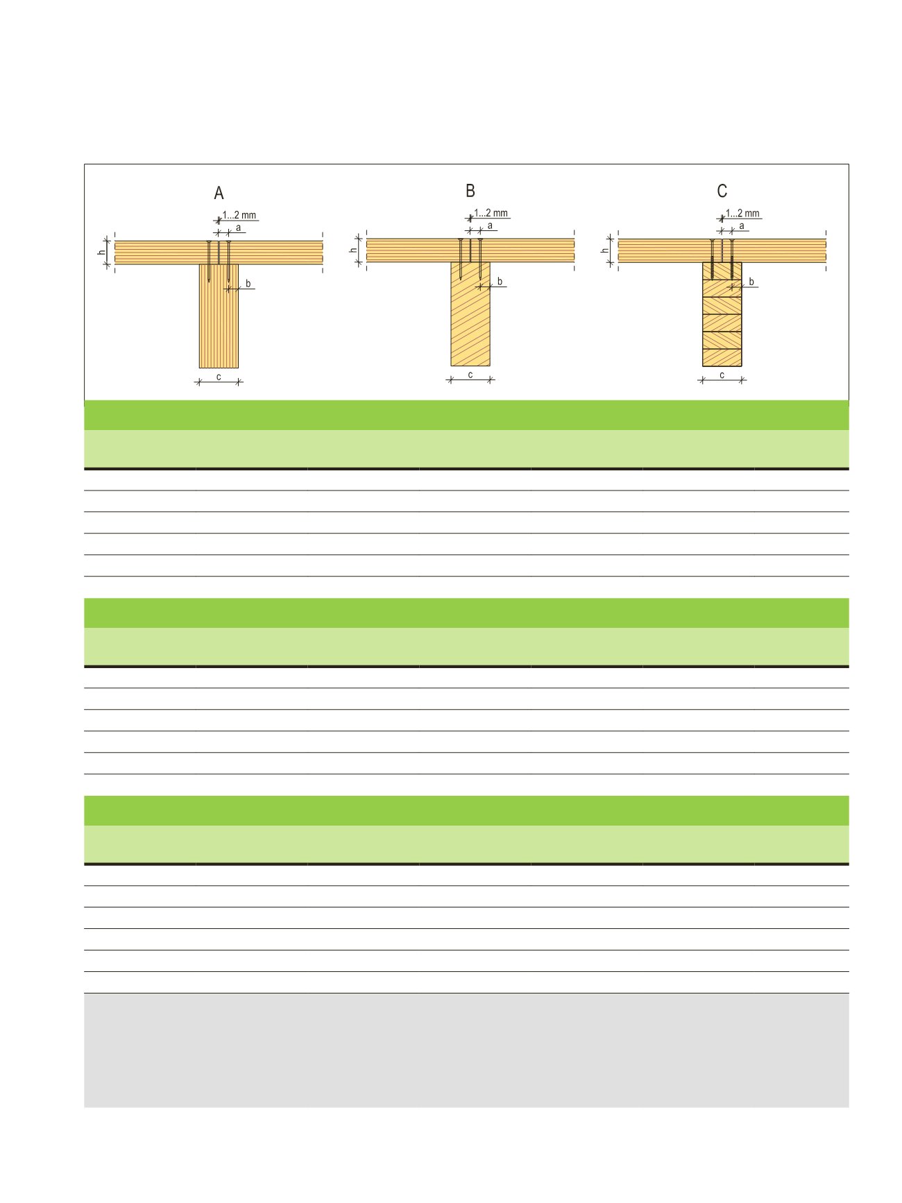
Predesign table for the lateral load-carrying capacity of connection between an LVL 36 C panel and LVL-P, glulam GL30c or solid
wood C24 frame; load-duration class between instantaneous and medium-term.
LVL 05, Table 5.5
A: LVL 36 C panels nailed with smooth round nails to LVL 48 P frame
h
1)
[mm]
d
2)
[mm]
L
min
3)
[mm]
≥
a
4)
[mm]
≥
b
5)
[mm]
≥
c
6)
[mm]
R
k
7)
[N]
24
2,1
50
11
15
51
470
27
2,5
60
13
18
63
600
33
2,8
70
14
20
69
750
45
3,1
90
16
22
75
900
57
3,4
100
17
24
84
1000
69
4,2
125
21
30
102
1500
B: LVL 36 C panels nailed with smooth round nails to GL30c or C24 frame
h
1)
[mm]
d
2)
[mm]
L
min
3)
[mm]
≥
a
4)
[mm]
≥
b
5)
[mm]
≥
c
6)
[mm]
R
k
7)
[N]
24
2,1
50
11
11
45
440
27
2,5
60
13
13
63
580
33
2,8
70
14
14
63
700
45
3,1
90
16
16
63
840
57
3,4
100
17
17
75
950
69
4,2
125
21
21
90
1350
C: LVL 36 C panels screwed to GL30c or C24 frame
h
1)
[mm]
d
2)
[mm]
L
min
3)
[mm]
≥
a
4)
[mm]
≥
b
5)
[mm]
≥
c
6)
[mm]
R
k
7)
[N]
24
4,5
60
23
23
100
1100
27
5,0
70
25
25
115
1300
33
5,0
70
25
25
115
1300
45
6,0
90
30
30
140
1800
57
7,0
100
35
35
165
2400
69
8,0
120
40
40
165
3000
1)
h
[mm] is the thickness of the LVL 36 C panel
2)
d
[mm] is the diameter of the nail or outer diameter of the threaded part of the screw
3)
L
min [mm] is the minimum length of the nail or screw
4)
a
[mm] is the end distance (5
d
) of the panel, edge distance may be 3
d
5)
b
[mm] is the edge distance (7
d
for LVL edge face and 5
d
for solid wood or glulam) of the beam
6)
c
[mm] is the minimum width of the beam
7)
R
k
[N] is the characteristic lateral load-carrying capacity of the connection
LVL Handbook Europe
157