



 157 / 228

5. STRUCTURAL DESIGN OF CONNECTIONS
where
f
ax,ε,1,k
is the characteristic withdrawal strength parameter
for a screw at the head side member of the connection
at an angle ε to the grain direction [N/mm
2
];
f
ax,ε,2,k
is the characteristic withdrawal strength parameter
for a screw at the pointside member of the connection
at an angle
ε
to the grain direction [N/mm
2
];
d
is the outer threaded diameter [mm];
l
g,1
is the penetration length of the threaded part in the
head side member [mm];
l
g,2
is the penetration length of the threaded part in the
pointside member [mm];
f
tens,k
is the characteristic tensile capacity of the screw
determined in accordance with EN 14592 [N];
f
head
is the characteristic pull-through parameter of the
screw for the associated density ρa [N/mm
2
];
d
h
is the head diameter [mm];
ρ
k
is the characteristic density of LVL [kg/m
3
]; and
ρ
a
is the associated density for
f
head,k
[kg/m
3
].
When the screwing direction in the beam is ε = 90° to the grain
direction (even though the angle
β
is inclined between the edge
face and the wide face), it is not allowed to add the tension ca-
pacity of the head to the withdrawal capacity of the treaded
part in the beam. Therefore the characteristic withdrawal ca-
pacity
R
T,k
of the screw is calculated by the equation:
R_(T,k)=min{█(max(f_(ax,90,1,k) d l_(g,1) ; f_(h (5.35)
The withdrawal strength
f
ax,ε,k
is determined by testing accord-
ing to EN 14592 and EN 1382 or it can be determined at angle
ε
to the grain as follows:
f_(ax,ε,k)=〖k_ax ∙ f〗_(ax,90,k)/(1,5 cos^2 β + s
(5.36)
32
where
ε
is the angle between the screw axis and the grain
direction, ε ≥ 15°, see Figure 5.12;
β
is the angle between the screw axis and the LVL’s wide
face, with 0°≤
β
≤ 90°, see Figure 5.7
k
ax
in according to the equation (5.29)
ρ
k
is the characteristic density of LVL [kg/m
3
];
ρ
a
is the associated density for
f
ax,k
[kg/m
3
]; and
f
ax,90,k
is the characteristic withdrawal strength parameter
for a screw perpendicular to the grain direction
[N/mm
2
]. It is determined by testing according to
EN 14592 and EN 1382 or for screws in LVL, it may be
assumed as
f
ax,90,k
=15 N/mm² for
ρ
a
= 500 kg/m³ and
screws 6 mm≤
d
≤ 12 mm in softwood LVL/GLVL
32
.
Tension screwed connection
In a joint consisting of only screws in tension, contact between
the wood members is required. Tension screw connection
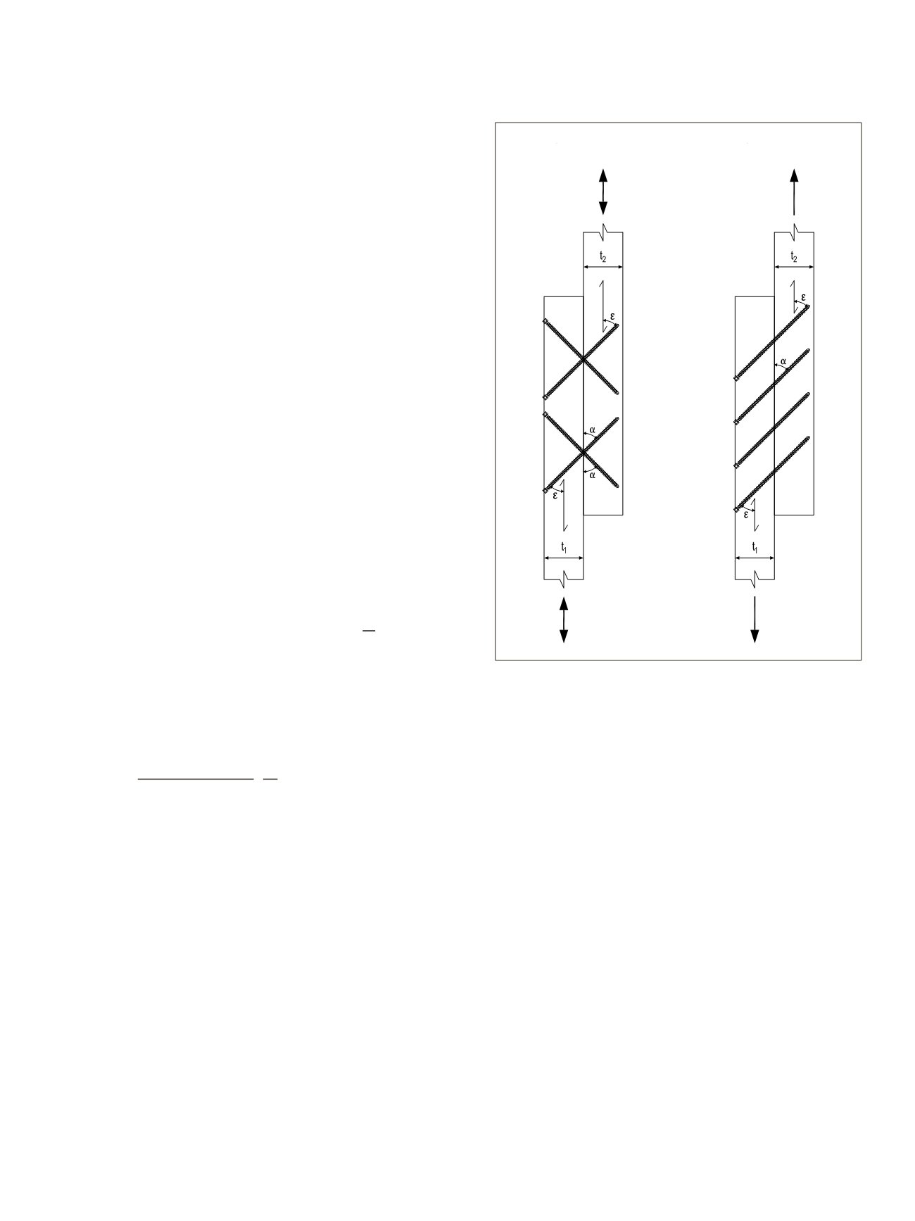
Figure 5.12.
Inclined screwed connections (A) cross screw
connection (B) tension screw connection
should not be used in conditions where wood drying could
cause a gap of over 0.2d. The gap is determined from the wood
shrinkage at a thickness of the LVL members in the screw
length (
L
∙ sin
α
)
31
.
The characteristic load-carrying capacity of the tension
screw connection, see Figure 5.12 (b), is calculated by the equa-
tion:
R
k
=
n
0,9
R
T,k
(cos
ε
+
μ
∙ sin
ε
)
(5.37)
where
n
is the number of screws in the connection;
R
T,k
is the characteristic withdrawal capacity, see (5.35);
α
is the angle between screw axis and the shear plane
(30° ≤ α ≤ 60°), see Figure 5.12 (b); and
μ
is the kinetic friction coefficient between the members,
the following values may be used:
0.26 for untreated LVL edgewise or LVL to timber or
timber-to-timber connections
0.30 for steel-to-timber connections
0.40 for untreated LVL flatwise connections
C,k
ax,ε,2,k g,2
0,8
tens,k
(5.29)
T,k
= min�
ax,ε,1,k
g,1
+
head,k
h2
�
a
�
0,8
ax,ε,2,k
g,2
tens,k
(5.30)
T,k
= min ⎩⎨ ⎧max �
ax,90,1,k
g,1
;
head,k
h2
�
k a
�
0,8
�
ax,ε,2,k
g,2
tens,k
(5.31)
ax,ε,k
=
ax
∙
ax,90,k
1,5 cos
2
+ sin
2
�
k a
�
0,8
(5.32)
32
A
B
188 (255)
T,k
= min { max (
ax,90,1,k
g,1
;
head,k
h2
(
k a
)
0,8
)
ax,ε,2,k
g,2
tens,k
(5.35)
The withdrawal strength
f
ax,ε,k
is determined by testing according to EN 14592 and EN 1382
or it can be determined at angle
ε
to the grain as follows:
ax,ε,k
=
ax
∙
ax,90,k
1,5 cos
2
+ sin
2
(
k a
)
0,8
(5.36)
32
where
ε
is the angle between the screw axis and
the grain direction
,
ε
≥ 15°, see Figure
5.11;
β
is the angle between the screw axis and the LVL’s wide face, with 0°≤
β
≤ 90°,
see Figure 5.7
k
ax
in according to the equation (5.29)
ρ
k
is the characteristic den ity of LVL [kg/m
3
];
ρ
a
is the associated density for
f
ax,k
[kg/m
3
]; and
f
ax,90,k
is the characteristic withdrawal strength parameter for a screw perpendicular to
the grain direction [N/mm
2
]. It is determined by testing according to EN 14592
and EN 1382 or for screws in LVL, it may be assumed as
f
ax,90,k
=15 N/mm² for
ρ
a
= 500 kg/m³ and screws 6 mm≤
d
≤ 12 mm in softwood LVL/GLVL
32
.
Tension screwed connection
In a joint consisting of only screws in tension, contact between the wood members is
required. Tension screw connection should not be used in conditions where wood drying
could cause a gap of over 0.2d. The gap is determined from the wood shrinkage at a
thickness of the LVL members in the screw length (
L∙
sin
α
)
31
.
The characteristic load-carrying capacity of the tension screw connection, see Figure 5.11
LVL Handbook Europe
155