



 153 / 228

5. STRUCTURAL DESIGN OF CONNECTIONS
Wood failure should be checked for at tension-loaded
member ends for connection force components that are par-
allel to the grain. There are two types of timber failure mode:
block shear and plug shear.
• Block shear needs to be checked for bolt and dowel connec-
tions and for screw connections when the centre member
is screwed from both sides and the screws are overlapping.
• Plug shear failure mode must be checked for steel-to-timber
connections with surface fasteners (nails, screws, nail plates
and shear plates). Plug shear must be checked also for ex-
ternal lamellas in cases where the dowels are shorter than
the overall thickness of the members in the connection. For
LVL-Cwide face bolt and dowel connections, both block and
plug shear failure modes must be checked.
• Block and plug shear capacities are not checked for connec-
tions where all fasteners are in a single row parallel to the
grain (
n
2
= 1).
• If the timber member
t
1
has fasteners from opposite sides
and the effective thickness
t
ef
≥ 0.5
t
1
, the block shear capac-
ity of steel-to-timber connections should also be checked.
• Block shear need not to be checked for bolt and dowel con-
nections when:
• the member thicknesses are
t
1
≥ 4
d
,
t
s
≥ 5
d
(inner
member)
• there are max. 4 fasteners in a row parallel to the grain, and
• the distance perpendicular to grain between bolts
a
2
≥ 5
d
or between dowels
a
2
≥ 4
d
., see Figure 5.11.
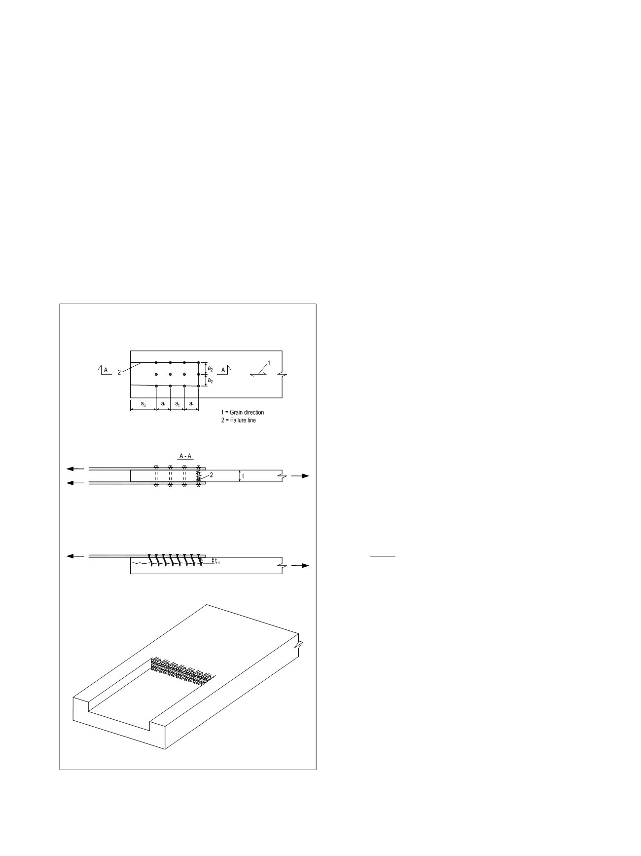
The characteristic plug shear capacity is calculated using the
equation:
F_(ps,k)=L_(net,t)∙(t_ef∙f_(t,0,k)+(a_3+(n_1-1)∙a_
(5.7)
where
L_(net,t)=(n_2-1)∙(a_2-D)
(5.8)
t_ef=R_k/(d∙f_(h,0,k) )
(5.9)
f
h,0,k
is the embedment strength according to subsection 5.5.1
or 5.6;
n
1
is the number of fasteners in rows parallel to the grain;
n
2
is the number of fastener rows perpendicular to the
grain;
a
1
is the fastener spacing parallel to the grain;
a
2
is the fastener spacing perpendicular to the grain;
a
3
is the fastener end distance;
D
is the hole diameter;
f
t,0,k
is the tension strength of the timber member:
35 N/mm
2
for LVL 48 P and 19 N/mm2 for LVL 36 C;
f
v,0,k
is the shear strength of the timber member:
f
v,0,flat,k
is 2.3 N/mm
2
for LVL 48 P and 1.3 N/mm
2
for LVL 36 C
in flatwise connections;
R
k
is the characteristic load-carrying capacity per shear
plane per fastener; and
d
is the fastener diameter.
Figure 5.11.
A) Block shear failure mode B) Plug shear failure
mode
31
A
B
5.3.3 Block shear and plug shear failure
modes at multiple dowel-type steel-to-
timber connections
Block shear and plug shear failure modes shall be checked for
steel-to-timber connections and tension-loaded member ends
of double or multiple shear plane timber-to-timber connec-
tions. The wood failure capacity of the joint area can be calcu-
lated according to the method presented in the Finnish Hand-
book for EC5: RIL 205-1-2009, Section 8.2.4S
31
. In addition,
the effective number of fasteners,
n
ef
, according to Section 5.3.2
are taken into account to prevent splitting and row shear fail-
ure mode. This method cannot be used for edgewise LVL con-
nections.
o
the distance perpendicular to grain between bolts
a
2
≥
4
d
., see Figure 5.10.
Figure 5.10. a) Block shear failure mode b) Plug shear failure mod
block shear failure 190320, Kuva_118_2 plug shear failure 19031
The characteristic plug shear capacity is calculated using the equ
ps,k
=
net,t
∙ (
ef
∙
t,0,k
+ (
3
+ (
1
− 1) ∙
1
∙
v,0,k
))
ere
net,t
= (
2
− 1) ∙ (
2
− )
ef
=
k
∙
h,0,k
o
the distance perpendicular to grain between bolts
a
2
≥
4
d
., see Figure 5.10.
Figure 5.10. a) Block shear failur ode b) Plug shear failure mod
block shear failure 190320, Kuva_118_2 plug shear failure 19031
The characteristic plug shear capacity is calculated using the equ
ps,k
=
net,t
∙ (
ef
∙
t,0,k
+ (
3
+ (
1
− 1) ∙
1
∙
v,0,k
))
where
net,t
= (
2
− 1) ∙ (
2
− )
ef
=
k
∙
h,0,k
LVL Handbook Europe
151