



 151 / 228

5. STRUCTURAL DESIGN OF CONNECTIONS
Table 5.4.
Minimum spacings, end distances and edge distances for 6-30 mm dowels
32
.
5.3 WOOD FAILURE MODES OF
CONNECTIONS
5.3.1 Risk of splitting due to connection
forces at an angle to the grain of face
veneers
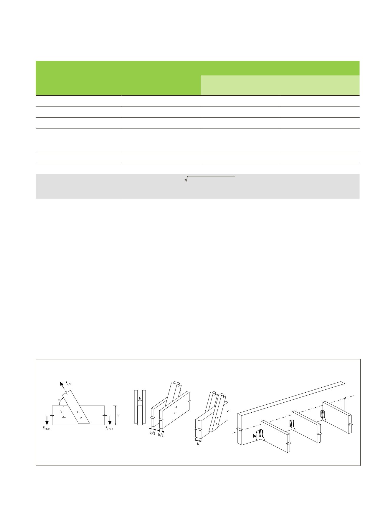
When a force in a connection acts at an angle to the grain (see
Figure 5.8) the possibility of splitting caused by the tension
force component, FEd ∙sin α, perpendicular to the grain, shall
be taken into account. For timber, glulam and LVL-P the fol-
lowing should be satisfied:
F
v,Ed
≤
F
90,Rd
(5.1) (EC5 8.2)
Figure 5.9.
Inclined force transmitted by a connection (modified from EC5 Figure 8.1)
where
F
90,Rd
is the design splitting capacity;
F
v,Ed
≤max{█(F_(v,Ed,1)@F_(v,Ed,2) )┤
(5.1) (EC5 8.3)
F
v,Ed,1
and
F
v,Ed,2
are the design shear forces on either side of
the connection caused by the connection force component
(
F
Ed
∙ sin α) perpendicular to the grain.
Spacing or distance,
see Figures 5.4-5.7
Angle α
Minimum spacing or end/edge distance
LVL-P / GLVL-P or
LVL-C / GLVL-C edge face
LVL-C / GLVL-C wide face
Spacing
a
1
(parallel to grain)
0° ≤ α ≤ 360°
(4 + 3
│
cos α
│
)
d
a)
(3 +
│
cos α
│
)
d
Spacing
a
2
(perpendicular to grain)
0° ≤ α ≤ 360°
3
d
3
d
Distance
a
3,t
(loaded end)
-90° ≤ α ≤ 90°
max (7
d
; 105 mm)
b)
max (4
d
; 60 mm)
c)
Distance
a
3,c
(unloaded end)
90° ≤ α < 150 °
150° ≤ α < 210°
210° ≤ α ≤ 270°
a
3,t
│
cos α
│
3
d
a
3,t
│
cos α
│
(3 +
│
cos α
│
)
d
Distance
a
4,t
(loaded edge)
0° ≤ α ≤ 180°
max [(2 + 2 sin α)
d
; 3
d
]
max [(2 + 2 sin α)
d
; 3
d
]
Distance
a
4,c
(unloaded edge)
180° ≤ α ≤ 360°
3
d
3
d
a)
minimum spacing
a
1
may be reduced to 5
d
if
f
h,0,k
is multiplied by a
1
/ (4 + 3
│
cos α
│
)
d
b)
minimum end distance
a
3,t
may be reduced to 7
d
for
d
< 15 mm if
f
h,0,k
is multiplied by
a
3,t
/105 mm
c)
minimum end distance
a
3,t
may be reduced to 4
d
for
d
< 15 mm if
f
h,0,k
is multiplied by
a
3,t
/ 60 mm
v,Ed
≤ max {
v,Ed,1 v,Ed,2
F
v,Ed,1
an
v,Ed,2
are the design shear forces on either side of the
connection f rce component (
F
Ed
∙ sin α
) perpendicular to the grai
Figure 5.8. Inclined force transmitted by a connection (
modified fr
(Kuva_107_a splitting force in connections 190314,
in connections 190314, Kuva_107_c splitting force in connections
Design splitting capacity is calculated from the characteristic splitti
equation (4.3), in subsection 4.1.6. For softwoods, the characteris
arrangement shown in Figure 5.8 should be taken as:
90,k
= 14 ∙ √
ℎ
e
(1 −
ℎ eℎ
)
[ ]
where
F
90,Rk
is the characteristic splitting capacity [Ν
];
h
e
is the loaded edge distance to the centre of the most
LVL Handbook Europe
149