



 150 / 228

5. STRUCTURAL DESIGN OF CONNECTIONS
Table 5.2.
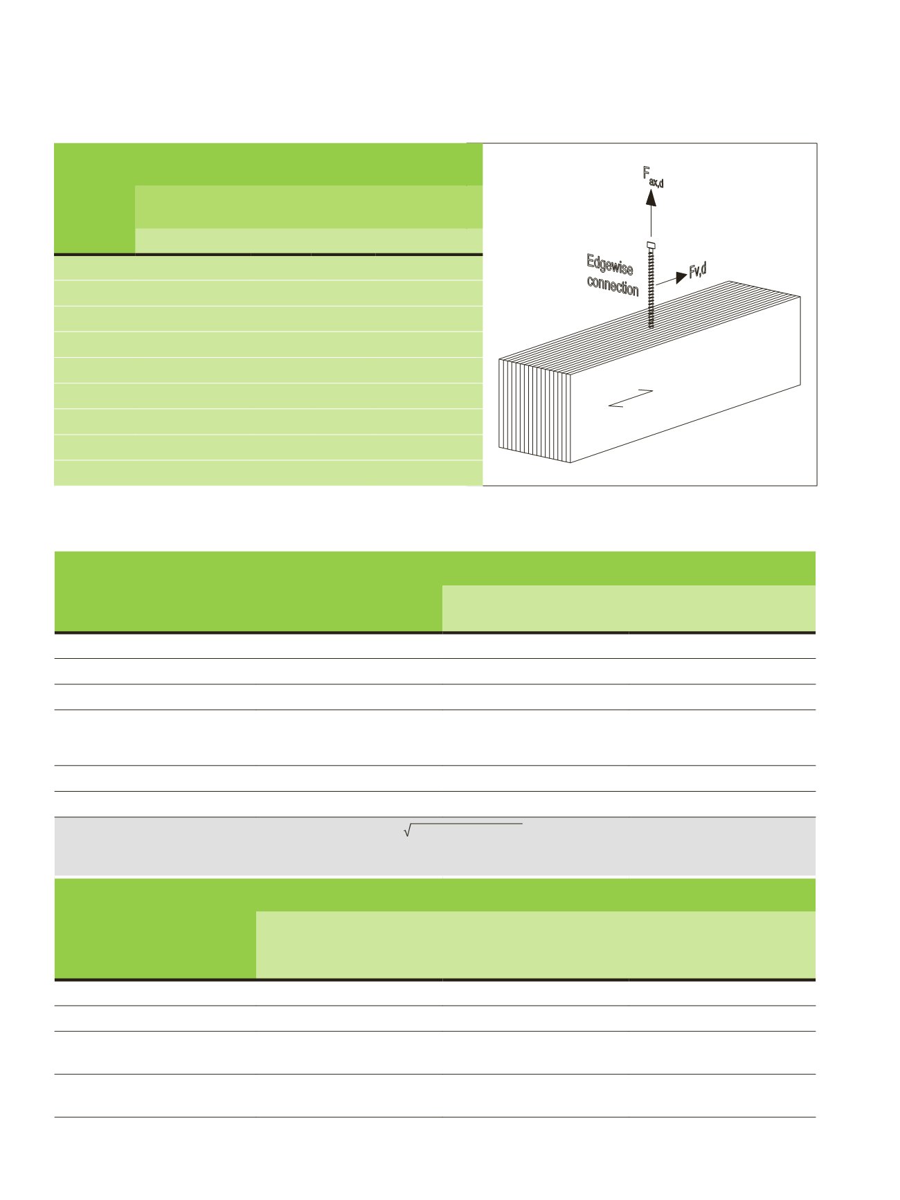
Maximum nail and screw size d [mm] for edge face (edgewise) connections
Table 5.3.
Minimum spacings, end distances and edge distances for bolts and screws with max outer thread diameter >12 mm with predrilled
holes
32
. Note: EN 1995-1-1:2004 (Eurocode has a limit of def < 6 mm which corresponds with 9 mm outer thread diameter.
LVL
thickness
Laterally loaded connections
Axially loaded
connections
Without pre-
drilling
a
4,c
≥ 7
d
With predrilling
a
4,c
≥ 3
d
a
2,CG
≥ 4
d
Nails and screws
Nails
Screws
Screws
27 mm
1,9
4,5
4,5
3,4
33 mm
2,4
5,5
5,5
4,1
39 mm
2,8
6,5
6,5
4,9
45 mm
3,2
7,5
7,5
5,6
51 mm
3,6
8,0
8,5
6,4
57 mm
4,1
8,0
9,5
7,1
63 mm
4,5
8,0
10,5
7,9
69 mm
4,9
8,0
11,5
8,6
75 mm
5,4
8,0
12,0
9,4
LVL 05, Table 5.3
• MUOKATTU 29.8.
Spacing or distance,
see Figures 5.4-5.5 and 5.7
Angle α
Minimum spacing or end/edge distance
LVL-P / GLVL-P or
LVL-C / GLVL-C edge face
LVL-C / GLVL-C wide face
Spacing
a
1
(parallel to grain)
0° ≤ α ≤ 360°
(4 + 3
│
cos α
│
)
d
a)
4
d
Spacing
a
2
(perpendicular to grain)
0° ≤ α ≤ 360°
4
d
4
d
Distance
a
3,t
(loaded end)
-90° ≤ α ≤ 90°
max (7
d
; 105 mm)
b)
max (4
d
; 60 mm)
c)
Distance
a
3,c
(unloaded end)
90° ≤ α < 150 °
150° ≤ α < 210°
210° ≤ α ≤ 270°
(1 + 6 sin α)
d
4
d
(1 + 6 sin α) d
4
d
4
d
4
d
Distance
a
4,t
(loaded edge)
0° ≤ α ≤ 180°
max [(2 + 2 sin α)
d
; 3
d
]
max [(2 + 2 sin α)
d
; 3
d
]
Distance
a
4,c
(unloaded edge)
180° ≤ α ≤ 360°
3
d
3
d
a)
minimum spacing
a
1
may be reduced to 5
d
if
f
h,0,k
is multiplied by a
1
/ (4 + 3
│
cos α
│
)
d
b)
minimum end distance
a
3,t
may be reduced to 7
d
for
d
< 15 mm if
f
h,0,k
is multiplied by
a
3,t
/105 mm
c)
minimum end distance
a
3,t
may be reduced to 4
d
for
d
< 15 mm if
f
h,0,k
is multiplied by
a
3,t
/ 60 mm
Spacing and end/edge
distances on circular
patterns for double shear
moment-resisting
connections, see Figure 5.6
Minimum spacing or distance
LVL-P, GLVL-P wide face
LVL-C / GLVL-C wide face
Side member
LVL-C / GLVL-C wide face
Middle member
LVL-P, GLVL-P or LVL-C wide face
a
1
(spacing on circle)
6
d
4
d
5
d
a
2
(spacing between circles)
5
d
4
d
5
d
a
3,t
(loaded end)
6
d
4
d
6
d
in middle member
4
d
in side member
a
4,t
(loaded edge)
4
d
3
d
4
d
in middle member
3
d
in side member
148
LVL Handbook Europe