



 167 / 228

6. PERFORMANCE OF LVL IN FIRE
6.4.4 LVL-C panel as a protection against
fire exposure
When the LVL-C panel thickness is according to Table 6.3, the
panel protects a wooden structure behind it for a certain fire
resistance time t [min]. Other fire design calculations of the
remaining wooden structure are not needed unless the panel
is a part of the load-bearing system also in the structural fire
design. In the case of timber frame assemblies, the LVL-C pro-
tection panel thickness hp1 [mm] is calculated for the required
fire protection time t based on EN1995-1-2, equation (4.1) and
(C.7) or (D.3):
Minimum panel thickness
h
p1
=
β
0
∙ (
t
+4min)+7mm (6.5)
When the protection panel is applied directly on beams or col-
umns, the protection panel thickness
h
p2
[mm] is calculated for
the required protection time t based on EN1995-1-2 equations
(4.1) and (3.10):
Minimum panel thickness
h
p2
=
β
0
∙
t
+7mm
(6.6)
6.4.5 Summary of LVL-C panels for fire
protection
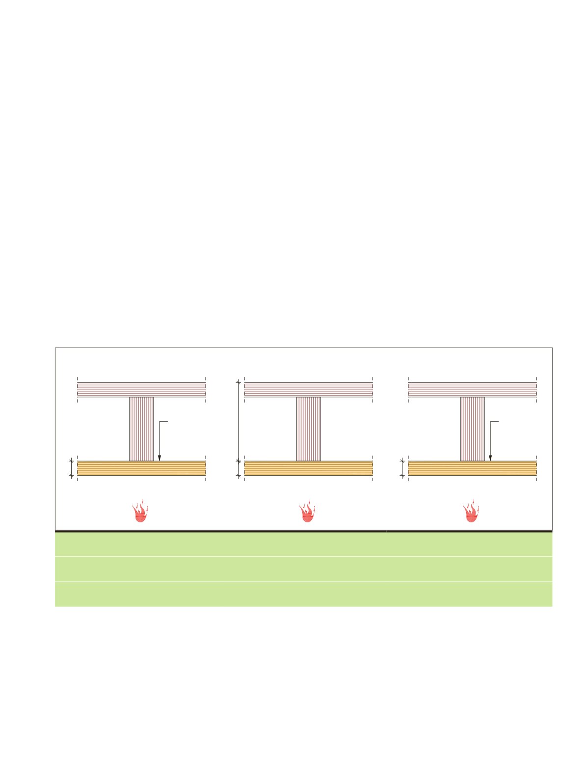
Table 6.10 specifies the minimum thickness hp of LVL-C panel
when used as a covering with fire protection ability for the un-
derlying materials (column A), fire protection of the structures
(column B) or when used as a ceiling structure which has a fire
resistance requirement EI (column C). All of the different fire
protection specifications also have requirements for the detail-
ing of, e.g., joints between the panels.
Figure 6.10.
Minimum LVL 36 C panel thicknesses in fire protection applications.
A)
The fire protection ability K2 class requirement for protecting the underlying material is that behind the protection panel the average
temperature rise over the whole of the unexposed surface is limited to 250 °C and the maximum temperature rise at any point of that
surface does not exceed 270 °C. Note that in some cases there can be additional requirements to use only non-combustible materials for the
covering.
B)
LVL panel as fire protection. When the panel thickness
h
p
=
d
char,0
+
k
0
∙7 mm, it protects the underlying structure for a required fire resistance
time t and the effective cross-section in the resistance calculation is the entire underlying structure.
C)
The separating function
EI
is assumed to be satisfied when integrity
E
and insulation
I
are maintained. When LVL-C panel is used as a ceiling
structure and has a fire resistance requirement of
EI
, the required panel thicknesses
h
p
can be determined according to EN1995-1-2 Annex
E based on the insulation time
t
ins
. In addition, the requirements for the detailing of joints shall be fulfilled. Note: An advanced calculation
method for separating function is presented in the publication
Fire safety in timber buildings –Technical guideline for Europe
, chapter 5.5
40
LVL 06, Figure 6.10
K
2
10, when
h
p
≥ 15 mm
Fire protection for 15 min,
when
h
p
≥ 18 mm
Insulation time
t
ins
= 15 min,
when
h
p
≥ 18 mm
K
2
30, when
h
p
≥ 26 mm
Fire protection for 30 min,
when
h
p
≥ 29 mm
Insulation time
t
ins
= 30 min,
when
h
p
≥ 33 mm
K
2
60, when
h
p
≥ 52 mm
Fire protection for 60 min,
when
h
p
≥ 49 mm
Insulation time
t
ins
= 60 min,
when
h
p
≥ 66 mm
A
B
C
Panel as K
2
classified covering
Panel as fire protection
Panel as ceiling with El requirement
Increase
250°C
(max 270°C)
Increase
140°C
(max 180°C)
Underlying structure
h
p
h
p
h
p
LVL Handbook Europe
165