



 116 / 228

4. STRUCTURAL DESIGN OF LVL STRUCTURES
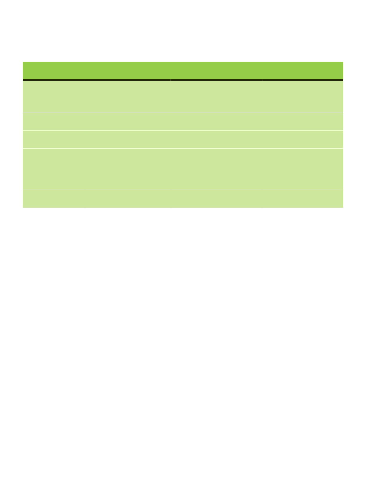
Table 4.1.
Load-duration classes and examples of loads
31
.
in load is defined by multiplying the characteristic value of a
load Q
k
by factor ψ
0
, ψ
1
or ψ
2
depending on the case:
• Characteristic combination (ψ
0
Q
k
) is used for verification of
ultimate limit states and for irreversible (permanent) defor-
mations of a structure in serviceability limit states
• Frequent combination (ψ
1
Q
k
) is used for verification of ulti-
mate limit states involving accidental actions and for verifi-
cation of reversible deformations of a structure in servicea-
bility limit states
• Quasi-permanent combination (ψ
2
Q
k
) is used for verifica-
tion of ultimate limit states involving accidental actions and
for verification of reversible serviceability limit states. Qua-
si-permanent values are also used for the calculation of long-
term effects.
Factor ψ
2
can be concluded as a factor that converts short-term
loads to permanent loads which have a similar long-term influ-
ence in the calculation of creep deformations.
Loads are defined in EN 1991 and the load combinations
in EN 1990. The rules in these standards define how permanent
actions and variable actions shall be taken into consideration in
load combinations. The general equation of load combination
in the ultimate limit state is:
E
d
=
∑
j≥1
γ
G,j
∙
G
k,j
+
γ
Q,1
Q
k,1
+
∑
i≥1
γ
Q,i
∙
ψ
0,i
∙
Q
k,i
(4.1)
where
γ
G,j
= partial safety factor for permanent actions j;
G
k,j
= characteristic value of permanent load j;
γ
Q,1
= partial safety factor for decisive variable action 1;
Q
k,1
= characteristic value of decisive variable load 1;
γ
Q,i
= partial safety factor for variable action i;
Q
k,I
= characteristic value of variable load i; and
ψ
0,i
= reduction factor in load combination for variable action i.
The values of
γ
G
and
γ
Q
are set in national annexes, but in com-
mon ULS design cases for unfavourable actions
γ
G
= 1,15 - 1,35
and
γ
Q
= 1,5 - 1,6. In SLS design
γ
G
and
γ
Q
are 1,0.
4.1.2 Consequence class, reliability class
and factor
K
FI
For the purpose of reliability differentiation, consequences
classes (CC1-CC3) may be established by considering the con-
sequences of a failure or malfunction of the structure. Class
CC1 is used for low consequence for loss of human life or when
economic, social or environmental consequences are small or
negligible. For example, agricultural buildings and storage
houses may belong to class CC1. CC2 is a normal class with a
medium consequence level and is used as a default class for res-
idential and office buildings. CC3 is used for buildings where
the consequences of failure are high such as concert halls or
similar monumental structures.
The requirements for different consequence classes are set
in the associated reliability classes RC1-RC3. They include re-
quirements for the level of reliability index
β
, the supervision
of design and execution of the structures and resistance prop-
erties of materials and products. In partial safety factor design
the reliability classes are taken into account by the
K
FI
factor
for actions. The values of K
FI
are given in national annexes, but
according to the default values of EN1990, in RC1 the actions
in equation (4.1) of the ULS are multiplied by K
FI
= 0,9, in RC2
by K
FI
= 1,0 and in RC3 by K
FI
= 1,1. K
FI
is not used in SLS.
Load-duration class Order of accumulated
duration of characteristic load Examples of loading
Notes
Permanent
More than 10 years
• Self-weight
• Permanently installed machinery
• Compartment walls in some
countries
Long-term
6 months – 10 years
• Long-term storage
Medium-term
1 week – 6 months
• Medium-term imposed floor load
• Snow
Snow in Finland
Short-term
Less than one week
• Short-term snow
• Wind
• Staircase loads
• Imposed point loads
• Service maintenance loads on roofs
Snow in several countries
Wind in several countries
Instantaneous
• Instantaneous wind
• Accidental load
Wind in Finland
d
= ∑
G,j
∙
k,j
+
j≥1
Q,1 k,1
+ ∑
Q,i
∙
0,i
∙
k,i
i≥1
(4.1)
114
LVL Handbook Europe