



 54 / 228

2. LVL STRUCTURES IN FLOORS, WALLS, ROOFS AND IN SPECIAL APPLICATIONS
LVL joist floors can be built on a wooden, steel or concrete
frame or walls. The 1:8 width to depth ratio of rigid LVL-P
joists is ideally suited to the structural depths of floor con-
structions even with long spans. The recommended minimum
width of supports and LVL floor joists is 45 mm in order to
provide proper support for decking panels.
Floor elements can be prefabricated off-site. This saves
time on the construction site, reduces waste, and improves
quality as the elements can be made in dry factory conditions.
An element floor usually has a slightly higher material con-
sumption as the edge joists that seal the elements at the sides
form double joists in the completed floor structure.
Floor deflections and vibrations are not only dependent on
the floor joists themselves, but on the decking on the joists and
on the blockings installed for transverse bracing perpendicular
to the span of the floor. Due to the rigidity of typical decking
panels, a joist spacing of c/c 400 mm is recommended. The
spacing should not exceed 600 mm to avoid excessive deflec-
tion of the panels in the perpendicular direction to the joists.
It is also recommended to glue the decking panels to the joists
with polyurethane adhesive for best results. Depending on the
gluing conditions (on-site or off-site) and country-specific re-
quirements, at least half of the advantage of the composite ef-
fect of gluing can be utilized in structural calculations.
Blockings between the joists reduce deflection under point
loads, but they need to be fixed well to the joists to give the
desired transverse stiffness and to avoid creaking in the long
term. The best improvement can be achieved by fixing the
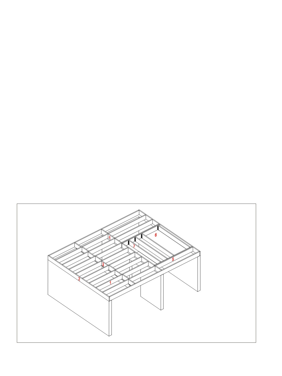
Figure 2.4.
LVL-P joist floor members and details.
1. Floor joist
2. Rim board
3. Blockings at the centre of a span
4. Blockings at support
5. Trimmer beam
6. Staircase opening, trimmer connection
7. Joist hanger connection
blockings to a transverse tension flange board installed under
the floor joists, see Figure 2.6.
Multi-span structures reduce deflection and enable longer
maximum span lengths compared to single-span structures.
However, if the floor joists are continuous between separate
rooms more conservative span lengths are recommended as
people are more sensitive to vibrations originating from spaces
external to the space that they are occupying.
Floor vibration is controlled in the design based on: 1)
deflection under point 1kN load when the lowest natural fre-
quency
f
1
is higher than 8-9 Hz depending on country-specific
design rules and 2) acceleration when f1 is 4,5-8 Hz. It is rec-
ommended to design joist floors to
f
1
> 8 Hz, because achiev-
ing the requirements of the acceleration criterion requires the
addition of considerable extra weight to the structure. For more
information on floor vibration design, see subsection 4.3.7.
Residential floors within apartments can be light, with-
out acoustic or fire resistance requirements, in which case de-
flection under 1kN point load is the governing requirement.
Intermediate floors between apartments require protective
cladding underneath the floor and extra mass on the top of
the floor, which usually make the fundamental natural fre-
quency
f
1
> 8-9 Hz the most critical requirement. Figures 2.7
and 2.8 gives the maximum span lengths for different joist
sizes. Span lengths up to ~6 m can be achieved with normal
floor thicknesses, but with the biggest joists over 8 m spans
are possible.
52
LVL Handbook Europe