



 51 / 228

1.13 JOINTS BETWEEN LVL PANELS
Structurally supported or self-supported joints may be used for
the connections of LVL-C panels. The load-bearing capacity
depends on the project and must be verified case-specifically,
including the connector diameter, minimum insertion depths,
spacing, and edge distances. For connector positioning, the
acting force direction is parallel to the joint as a default.
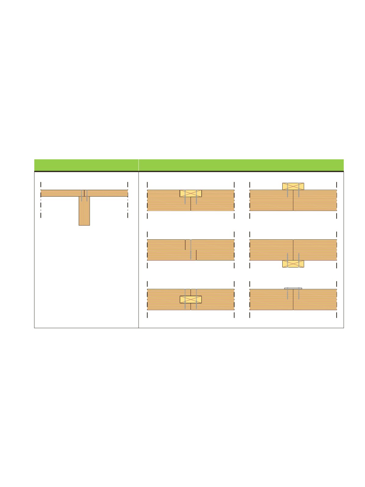
Figure 1.67 illustrates the principles of panel jointing. In
structurally supported panel joints, the panel edges are usually
straight and the force acting parallel to the joint is transferred
through the load-bearing structure from one panel to the next.
Figure 1.67.
Structurally supported joint and self-supporting joints of LVL-C panels.
Where other structural features allow, a simple solution for a
self-supporting joint is to use straight-edged panels and fas-
ten a wooden or steel batten on or under them. Otherwise,
the edges of the panels require machining. A common type
of machined joint is a half-lap connection where part of the
panel thickness is machined to create matching pairs of edges.
A separate batten can be placed on the half-lap edges as a sur-
face spline or as an interior spline when the edges are grooved
to a tongue profile. Suitable nail and screw sizes are defined in
Section 4.7.
1. LVL AS A CONSTRUCTIONMATERIAL
LVL 01, Figure 1.58
Structurally supported joint
Self-supported joints
LVL Handbook Europe
49