



 29 / 228

1. LVL AS A CONSTRUCTIONMATERIAL
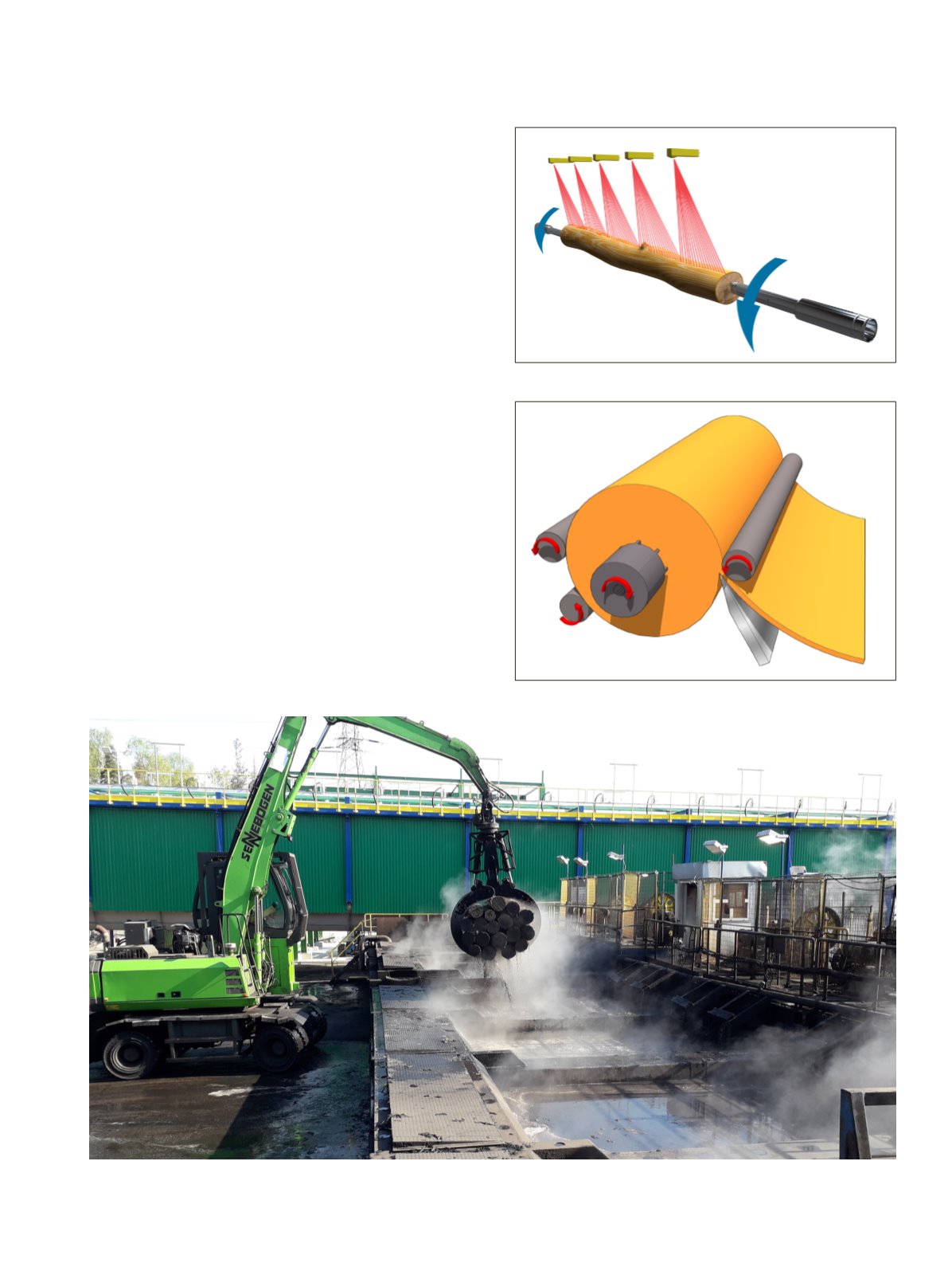
Figure 1.25.
Peeler blocks being lifted from a conditioning chamber.
Figure1.26.
XY centring device with laser scanning
Figure1.27.
Peeling method
The logs are cut to the required peeler block lengths on an
automatic saw line and transferred to the debarker. The debark-
er removes the bark down to the cambium so that the blocks
are free of bark. During debarking, damage to the peeler block
surface is carefully avoided, as the most valuable veneer qual-
ities are obtained from the outermost layers of the wood dur-
ing peeling.
The conditioning increases the internal temperature of the
blocks andmakes the wood softer for peeling. In northern win-
ter conditions the logs are thawed by soaking them in covered
and heated conditioning chambers.
1.6.2 Blocks to veneer
A jack-ladder lifts the blocks one by one to the charger for XY
centering. The block charger plays a key role in optimizing raw
material utilization and the value of the veneer yield. To recov-
er the maximum amount of veneer from the block, the block
is optimally aligned between the lathe spindles using high pre-
cision laser measurement.
In the lathe, the peeler block is rotated between the spin-
dles at a constant speed while the knife carriage moves toward
the block core. For LVL production, the typical nominal thick-
ness for softwood veneer is 3 mm. According to EN14374, the
maximum thickness of veneers in structural LVL is 6 mm. The
veneer is peeled through the gap between the peeler knife and
the overhead nose bar. The knife gap is smaller than the veneer
thickness to ensure sufficient compression and high-quality
veneer.
LVL Handbook Europe
27