



 211 / 228

9. CALCULATION EXAMPLES OF LVL STRUCTURES
9.10 BRACING OF A STUDWALL
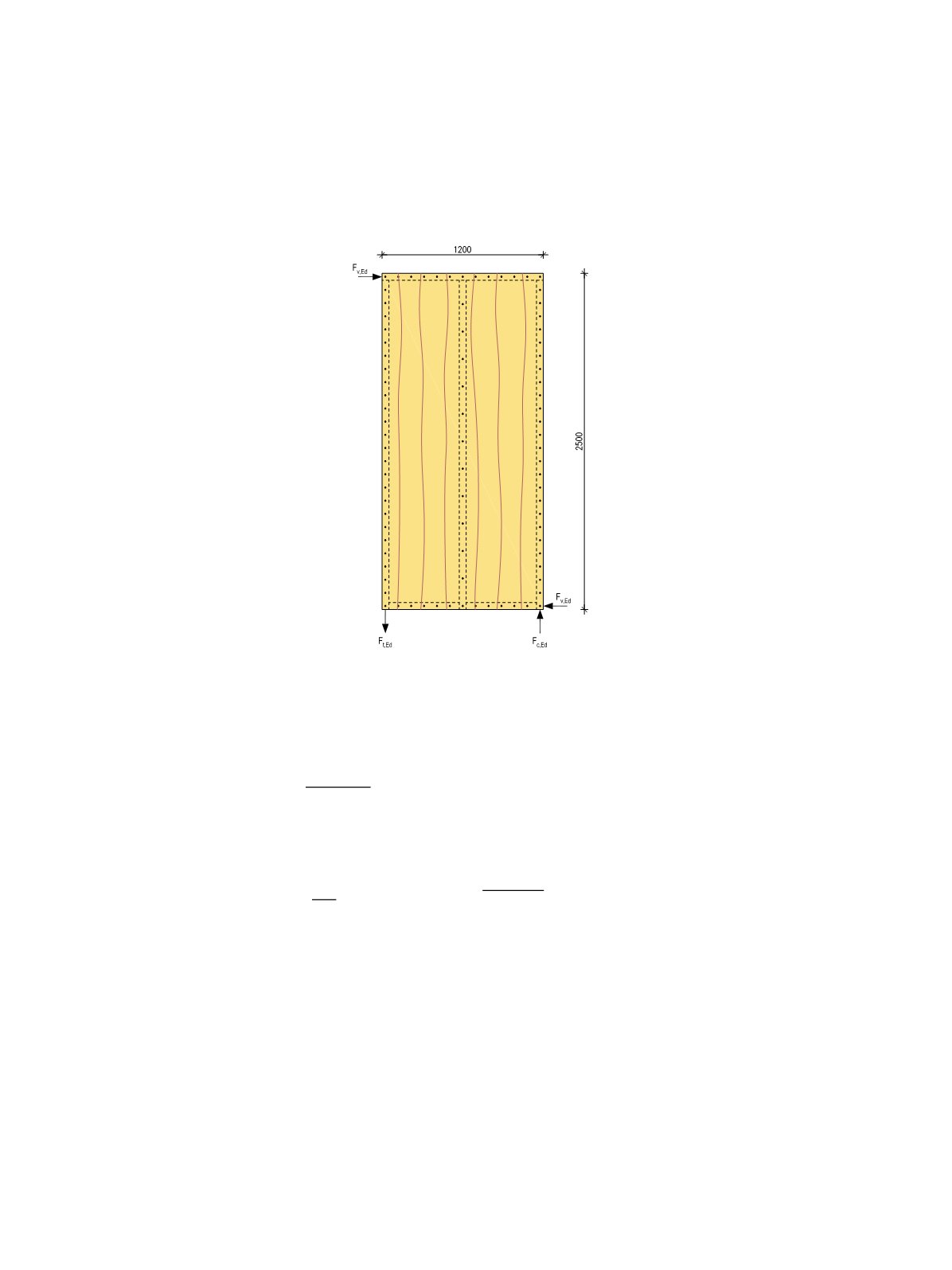
Define the maximum value of the horizontal force
F
V,Ed
from instantaneous wind load when LVL 36 C panel
27 mm x 1200 mm x 2500 mm is used for wall diaphragm. The panel is nailed to the LVL 48P wall studs, sole
plate and top binder with 2,5x60mm round nails. The studs are 51 x 150 mm in spacing
b
net
= 600 mm. The
nail spacing is a constant 100 mm at the perimeters and 200 mm at the centre stud. Service class SC1.
The design load-carrying capacity
F
V,Rd
(design racking resistance) under a horizontal force FV,Ed from wind
load acting at the top of a cantilever panel secured against uplift is determined using the simplified method A
of Eurocode 5 in section 9.2.4.2.
F_(V,Rd)=(F_(f,Rd)∙b∙c)/s
where
b
= panels width 1200 mm
c = {█(1,when b≥h/2@b/(h/2),when b<h/2)┤→c=(2500 mm)/(1200 mm)=0,96
s
= nail spacing in perimeters = 100 mm
F
f,Rd
= lateral design capacity of an individual fastener FV,nail,Rd multiplied by 1,2 (EC5 9.2.4.2 (5).
F
V,nail,Rd
is the minimum of failure modes (
a
) –(
f
) calculated from EC5 8.2.2, equation (8.6).
Geometry requirements of nail connections:
Pointside penetration length
t
2
should be at least 8d= 8∙2,5 mm = 20 mm. Nail length l = 60 mm – panels
thickness 27 mm = 33 mm > 20 mm → OK.
The penetration length t1 in LVL-C panel thickness should be at least 4
d
= 4∙2,5 mm = 10 mm → OK.
The unloaded edge distance
a
4,C
should be at least 3
d
= 3∙2,5 mm = 8 mm in the face side of LVL-C panel
and 7
d
= 7∙2,5 mm =18 mm in the LVL-P edge face. The minimum stud thickness is 2∙7
d
= 36 mm for a
perimeter stud and 2∙(7
d
+3
d
) + 1 mm = 51 mm when the panel joint is at a stud location, see Table 5.5
of panel joints.
LVL 36 C 27 x 1200 x 2500 mm
panel for wall diaphragm.
LVL 48 P 51 x 150 mm studs,
sole plate and top binder.
V,Rd
=
f,Rd
∙ ∙
b =
panels width 1200 mm
= � 1, when ≥ ℎ/2
ℎ/2 , when b < ℎ/2 → = 2500 mm 1200 mm = 0,96
s = nail spacing in perimeters = 1
F
f,Rd
= lateral design capacity of an individual fastener
F
V,nail,Rd
multiplied by 1,2
(EC5 9.2.4.2 (5).
F
V,nail,Rd
is the minimum of failure modes (
a
) –(
f
)
calculated from EC5 8.2.2, equation (8.6).
V,Rd
=
f,Rd
∙ ∙
b =
panels width 1200 mm
= � 1, when ≥ ℎ/2
ℎ/2 , when b < ℎ/2 → = 2500 mm 1200 mm = 0,96
s = nail spaci g in perimeters = 1
F
f,Rd
= lateral design capacity of an individual fastener
F
V,nail,Rd
multiplied by 1,2
(EC5 9.2.4.2 (5).
F
V,nail,Rd
is the minimum of failure modes (
a
) –(
f
)
calculated from EC5 8.2.2, equation (8.6).
LVL Handbook Europe
209