



 203 / 228

9. CALCULATION EXAMPLES OF LVL STRUCTURES
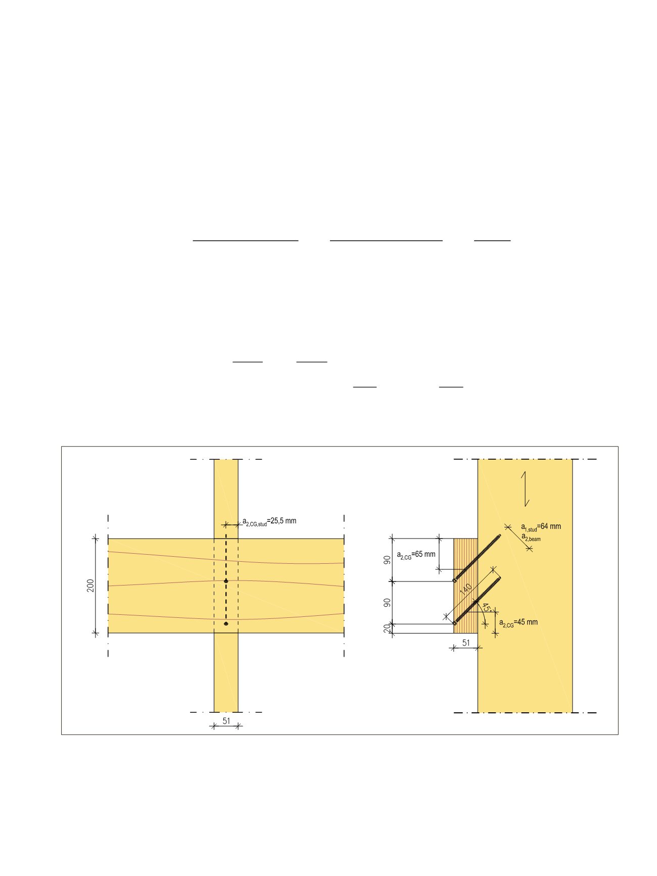
Geometry conditions:
Minimum distance to edge
a
2,CG
in stud ≥ 4
d
= 4∙6,0 mm = 24 mm. Stud thickness 51 mm/2 = 25,5 mm
→ Screw size 6,0x140 mm is OK for the stud
Min. screw spacing
a
1
in stud ≥ 10
d
= 60 mm
Min. screw spacing
a
2
in beam ≥ 5
d
= 30 mm
→
a
1
in the stud is more critical
Distance to edge of the beam
a
2,CG
≥ 4
d
= 24 mm. When the screwing angle is 45°, the beam thickness
t
1
/2 = 25,5 mm gives the minimum distance.
Maximum number of screws in the connection:
1+((h_beam – 2 ∙ min a_(2,CG) ))/((min a_(1,stud) / sin 45°) )=1+((200 mm – 2 ∙ 25,5 mm))/((60 mm
/ sin 45°) )=1+(149 mm)/(85 mm)=2,79
→ 2 screws are chosen for the connection, so that the heads of the screws are 20 mm and 110 mm from
the bottom edge of the beam.
1 + �ℎ
beam
– 2 ∙ min
2,CG
�
�min
1,stud
/ sin 45°� = 1 + (200 mm – 2 ∙ 25,5 mm)
(60 mm / sin 45°) = 1 + 149 mm 85 mm = 2,79
Minimum distance to the beam end
a
1,CG
≥ 10d = 60 mm. Therefore the end of the bean shall exceed the
stud edge.
Effective penetration length
l
ef,1
in ledger beam is
l_(ef,1)=l_(g,1)=t_1/sin〖45°〗 -l_u=(51 mm)/(sin 45°)-17 mm=55 mm
Penetration length in wall stud l_(g,2)=l-t_1/sin〖45°〗 =140 mm-(51 mm)/(sin45°)=68 mm
For the beam the angles in the connections are:
α
= 45°,
β
= 45° and
ε
= 90° and for the stud they are:
α
= 45°,
β
= 0° and
ε
= 45°.
ef,1
=
g,1
= t
1
sin 45° − l
u
= 51 mm sin 45° − 17 mm = 55 mm
enetration length in wall stud
g,2
= −
1
sin45°
= 140 mm −
51 mm sin45°
= 68 mm
k
=
0,9
T,k
(cos + sin )
(5.33)
T,k
= min ⎩⎨ ⎧max �
ax,90,1,k g,1
;
head,k h2
�
k a
�
0,8
�
ax,ε,2,k g,2
tens,k
(5.31)
ax,ε,k
=
ax
∙
ax,90,k
1,5 cos
2
+ sin
2
�
k a
�
0,8
(5.32)
ef,1
=
g,1
= t
1
si 45° − l
u
= 1 m sin 45° − 17 m = 5 m
Penetration lengt in all st d
g,2
= −
1
sin45°
= 140 m −
51 m sin45°
= 68 mm
k
=
0,9
T,k
(cos + sin )
(5.3 )
T,k
= min ⎩⎨ ⎧max �
ax,90,1 k g,1
;
head,k h2
�
k a
�
0,8
�
ax,ε,2 k g,2
tens,k
(5.31)
ax,ε,k
=
ax
∙
ax,90,k
1,5 cos
2
+ sin
2
�
k a
�
0,8
(5.32)
Connection capacity
The characteristic load-carrying capacity of the tension screw connection, see Figure 5.11(b), is cal-
culated by the equation:
R
k
=
n
0,9
R
T,k
(cos
α
+
μ
sin
α
)
(5.33)
LVL Handbook Europe
201