



 200 / 228

9. CALCULATION EXAMPLES OF LVL STRUCTURES
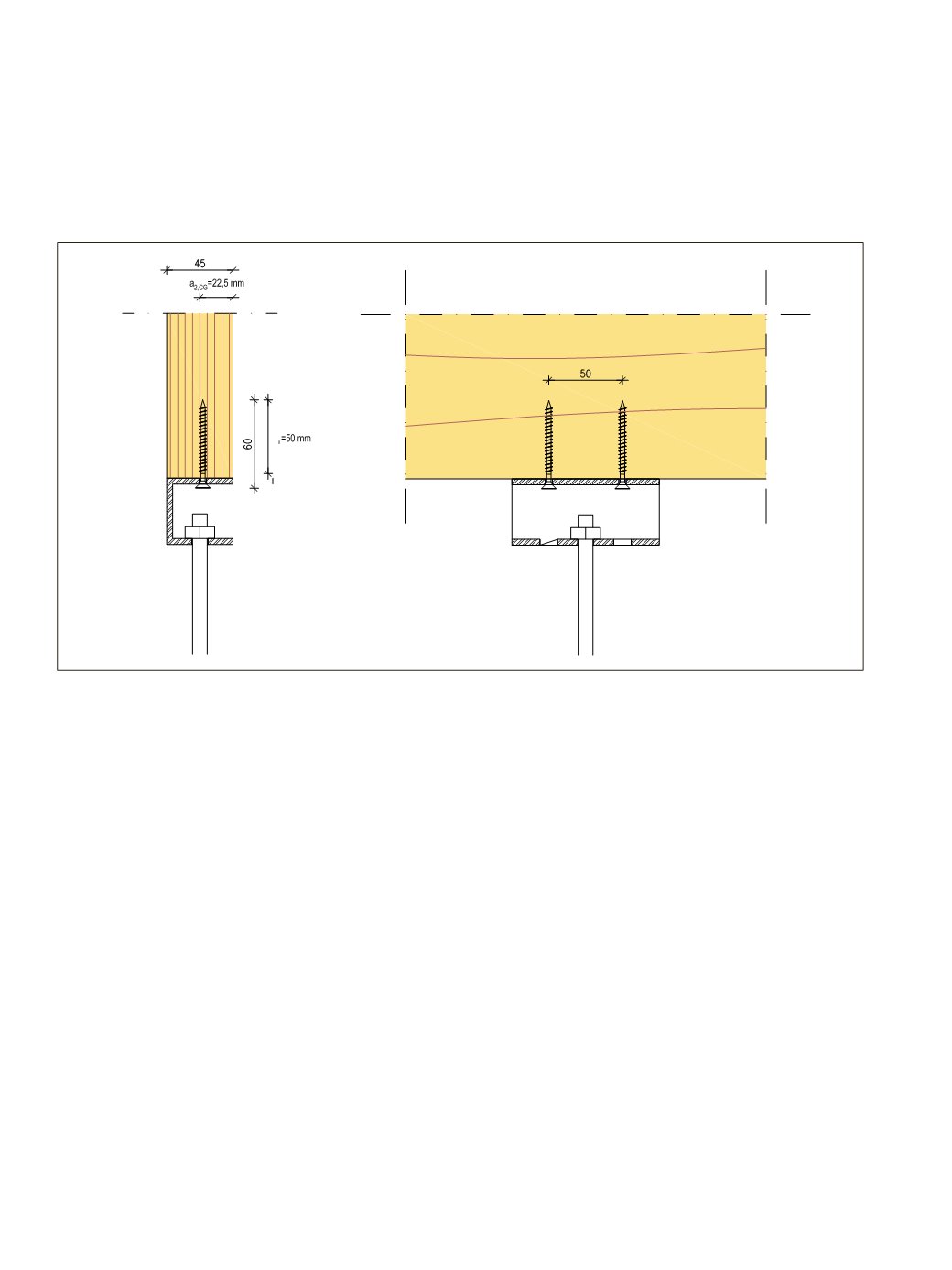
Screw properties
Size 5,0 x 60 mm screws, 2 screws / connection
Threaded length
l
g
= 50 mm
Head diameter
d
h
= 10 mm (Head pull-through capacity is not governing in steel-to-timber
connection)
Tensile strength
t
tens,k
= 7 kN determined in accordance with EN 14592.
t
tens,k
>
E
d,ULS
→ OK
Withdrawal strength
f
ax,k
= 10 N/mm
2
at the edge face of LVL 48 P, determined in accordance
with EN 14592
Modification factor
k
mod
for permanent load, SC1
= 0,6
Material safety factor
γ
M
for connections (default value in EC5) =1,3
9.6 AXIALLY LOADED SCREWCONNECTION AT THE EDGE FACE
An air duct is installed to the ceiling surface of roof element. Own-weight is 50 kg/m. Suspension connections
are c/c 2.5 m crosswise to roof element and the connections are made to the edge face of a 45mm thick LVL
48 P beams. Service class SC1.
Loading combination
The most critical ultimate limit state (ULS) load combination for the connection:
E
d,ULS
=
s
∙(
γ
G
∙
g
k
) = 2,5 m∙(1,35∙0,5 kN/m) = 1,7 kN
Note: Safety factor γ
G
for the case of only permanent loads according to Finnish National annex of
Eurocode 0.
198
LVL Handbook Europe